
Shop · Category
TOFD probes
Probes for the time-of-flight diffraction technique — used in pairs, selected to suit wall thickness and joint geometry.
 Exclusive distributor of the DOPPLER brand
PL · LT · LV · EE
Showing the single result
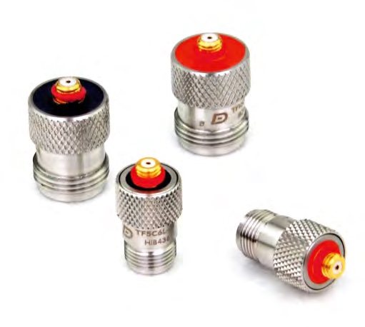
Conventional probe models (34)
Type a part number or pick the parameters. Click a model to open its series and send an inquiry.
| Part number | Type | MHz | Crystal [mm] | Crystal type | Angle |
|---|---|---|---|---|---|
| TF2C6N | TOFD | 2 | 6 | composite | — |
| TF2C10N | TOFD | 2 | 10 | composite | — |
| TF2C12N | TOFD | 2 | 12 | composite | — |
| TF2.25C6N | TOFD | 2.25 | 6 | composite | — |
| TF5C3N | TOFD | 5 | 3 | composite | — |
| TF5C6N | TOFD | 5 | 6 | composite | — |
| TF5C10N | TOFD | 5 | 10 | composite | — |
| TF7.5C6L | TOFD | 7.5 | 6 | composite | — |
| TF10C3N | TOFD | 10 | 3 | composite | — |
| TF10C6N | TOFD | 10 | 6 | composite | — |
| A45-3N | TOFD wedge | — | 3 | — | 45° |
| Φ3 45 | TOFD wedge | — | 3 | — | 45° |
| A60-3N | TOFD wedge | — | 3 | — | 60° |
| Φ3 60 | TOFD wedge | — | 3 | — | 60° |
| A70-3N | TOFD wedge | — | 3 | — | 70° |
| Φ3 70 | TOFD wedge | — | 3 | — | 70° |
| A45-6N | TOFD wedge | — | 6 | — | 45° |
| Φ6 45 | TOFD wedge | — | 6 | — | 45° |
| Φ6 S45-M12 | TOFD wedge | — | 6 | — | 45° |
| A60-6N | TOFD wedge | — | 6 | — | 60° |
| Φ6 60 | TOFD wedge | — | 6 | — | 60° |
| Φ6 S60-M12 | TOFD wedge | — | 6 | — | 60° |
| A70-6N | TOFD wedge | — | 6 | — | 70° |
| Φ6 70 | TOFD wedge | — | 6 | — | 70° |
| Φ6 S70-M12 | TOFD wedge | — | 6 | — | 70° |
| A45-10N | TOFD wedge | — | 10 | — | 45° |
| Φ10 45 | TOFD wedge | — | 10 | — | 45° |
| Φ10 S45-M12 | TOFD wedge | — | 10 | — | 45° |
| A60-10N | TOFD wedge | — | 10 | — | 60° |
| Φ10 60 | TOFD wedge | — | 10 | — | 60° |
| Φ10 S60-M12 | TOFD wedge | — | 10 | — | 60° |
| A70-10N | TOFD wedge | — | 10 | — | 70° |
| Φ10 70 | TOFD wedge | — | 10 | — | 70° |
| Φ10 S70-M12 | TOFD wedge | — | 10 | — | 70° |
Can’t find it? Send us the part number and we will match a model.
Send the part numberParameters as specified by the manufacturer. Cable length and connector are agreed in the quotation.
How the TOFD technique works
Pulse-echo inspection judges a flaw by the height of the reflected signal, so the result depends on how the discontinuity is oriented towards the beam. A few degrees of tilt can push an indication down or hide it completely. TOFD uses a different phenomenon: waves diffracted at the tips of a flaw. Signals from the upper and lower tip arrive at different times, and the depth and height follow from that time difference — regardless of orientation.
The inspection runs with a pair of probes facing each other across the weld. The distance between the beam exit points, the PCS, is set for the given thickness and it governs coverage. A TOFD image is read between two lines: the lateral wave running just below the surface and the backwall echo.
Choosing probes, and where the method ends
A TOFD probe needs a wide bandwidth and heavy damping so the pulse stays short — that is what decides whether two close tips can be resolved. The Doppler TOFD probe works with a delay line producing a refracted longitudinal wave in steel, with irrigated and carbide-tipped versions (TF1 series, for example TF1-L45-IHC) that survive longer scans.
The method has two well-known blind spots. Right under the surface the signal is lost in the lateral wave — the lateral wave dead zone. At the far wall the backwall echo gets in the way. That is why TOFD is combined with pulse-echo: a sector scan from Phased array probes (PAUT) or a creeping wave covers the near-surface region, while TOFD handles the bulk of the volume and the sizing. Height sizing can reach fractions of a millimetre in a well-chosen setup, but the real error depends on frequency, the number of points per A-scan and the tolerance on PCS (Ciorau, on tolerances of inspection parameters).
Frequently asked questions
Does TOFD replace phased array?
No, the techniques complement each other. TOFD is strong at height sizing and finds flaws regardless of orientation; phased array gives the cross-sectional image and covers the near-surface zone. The highest probability of detection comes from using both — which is why instruments such as Phascan II and the Novascan models carry separate TOFD channels beside the PA module.
Can phased array probes perform TOFD?
Yes. The array lets you change angle and effective PCS electronically, so several TOFD configurations are collected in one pass and the data merged into a single image. That helps on thick sections, where classic TOFD needed several probe pairs with different separations.
Which frequency for TOFD?
Ordinary welds are inspected at 3.5–5 MHz, a compromise between resolution and penetration. Higher frequencies resolve tips better but leave too little gain in reserve on thick, attenuating material. For thin walls you move towards smaller elements and a shorter PCS.