
 Catalogue 2026 · EN
Productcatalogue
Guangzhou Doppler Electronic Technologies Inc. — a professional supplier of instruments and complete solutions for industrial non-destructive testing.
Service to the community for the benefit of human safety Creating a world-class NDT brand
Profile
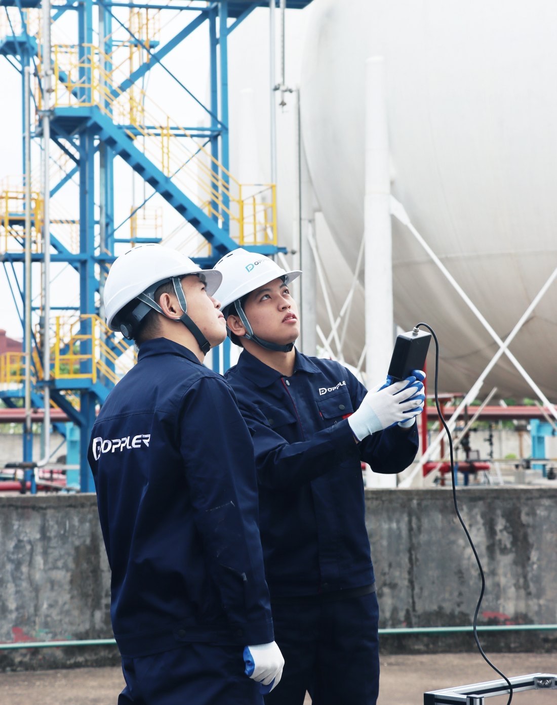
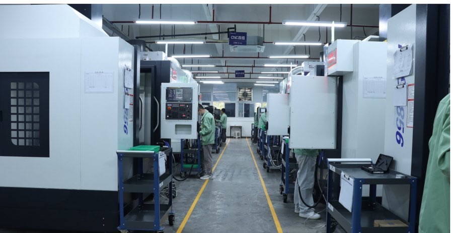
Established in 2008, the company Guangzhou Doppler Electronic Technologies INC (stock code: 301528) is a professional supplier of instruments and integrated solutions for industrial non-destructive testing (NDT). In 2023 the company was listed on the ChiNext board of the Shenzhen Stock Exchange; it holds the status of a national “specialized and innovative” Little Giant enterprise and of a high-technology enterprise.
Doppler specialises in phased array ultrasonic instruments, automated inspection systems, premium-class probes and dedicated analysis software. The company has achieved a breakthrough in the technology of 3D TFM high-resolution real-time imaging and in systems with 256 channels parallel transmission/reception, reaching a world-leading level.
In parallel, Doppler is building its competence in industrial radiography. The brand’s digital radiography (DR) and computed tomography (CT) systems are widely used in aerospace, the automotive industry, new-energy battery manufacturing, and on pressure vessels, castings, welded structures and precision electronics. With high-resolution imaging, AI-assisted analysis and integration with inspection automation, Doppler delivers efficient and reliable solutions both for laboratory evaluation and for high-volume production environments, meeting the strict quality and traceability requirements of advanced industry.
- Doppler was the first to achieve local production of phased array ultrasonic instruments and probes, breaking the monopoly of foreign suppliers.
- 3D-TFM imaging technology and the related manufacturing technologies have reached a world-leading level.
- The industry challenge of 256-channel parallel transmission and reception has been solved.
Applications
Catalogue contents
The full layout of the Doppler 2026 product catalogue with the original page numbering. This document covers all parts of the catalogue — instruments, phased array probes, scanners and conventional probes. A dot in place of a page number marks a model described within the group above but without its own entry in the brochure's contents.
Flaw detectors and UT boards 01
- NOVASCAN V3 — phased array UT flaw detector05
- NOVASCAN L3 — phased array UT flaw detector03
- NOVASCAN V2 — phased array UT flaw detector07
- NOVASCAN V1 — phased array UT flaw detector09
- PHASCAN II — portable PA flaw detector11
- FLEXSCAN — portable PA flaw detector13
- ROBUST P series — phased array UT boards15
- ROBUST M1 — multi-channel UT board17
- ROBUST S1 — single-channel UT board19
- ROBUST F1 — phased array UT board21
- ROBUST L1 — compact phased array UT board23
- Nexus F1 — pulser-receiver25
- Application examples27
Industrial Array Probe 02
- Linear array probes33
- Near-wall / immersion probes34
- Laterally focused array probes35
- Immersion / matrix array probes36
- Integrated wedge / water jacket probes37
- Soft protective film / wheel probes38
- Flexible / high temperature probes39
- R-angle / concave array probes40
- Bolt / spot welding probes41
- Dual-linear / dual matrix / wind power probes42
- Other Special Probes43
- Selection of Industrial Array Probes44
- Wedges45
- Connectors and Adapters46
Scanners 03
- Corrosion and Base Material Inspection49
- MOS08 — Modular Axial Stepping Scanner49
- DSC06 — Corrosion Scanner50
- FS01 — Corrosion Scanner·
- FS04 — Straight Pipe Flexible Probe Scanner50
- FS05 — Straight Pipe Concave Probe Scanner·
- FS06 — Elbow Scanner50
- LS03 — 64-element Tyre Scanner51
- LS06 — 128-element Tyre Scanner·
- LS13 / LS20 — Wind Turbine Blade Tyre Scanner·
- DSC03 — Heavy-duty Crawler51
- DSC05 — Small-diameter Longitudinal Scanner·
- DSC39 — Straight Pipe Internal Auto-scanner·
- DSC40 — Weld and Corrosion Auto-scanner·
- Weld Inspection53
- MOS01 — Mouse-type Scanner53
- MOS02 — Fillet Weld Scanner·
- MOS20 — Narrow-contact Surface Scanner·
- MOS43 — Weld Scanner for limited probe travel·
- CCE-2 — Simple Encoder53
- CCE-3 — TOFD Simple Bracket Scanner·
- CCE-4 — Weld Scanner with side guide·
- MOS03 — Weld Seam Bilateral Scanner54
- FC14 — Axial/Longitudinal Weld Scanner55
- FC29 — Simple Circumferential Scanner·
- FC30 — Manual Weld Inspection Scanner55
- FC26 — Negative Pressure Longitudinal Weld Scanner·
- FC44 — Suction Cup Weld Scanner·
- CRS7/CRS8 — Modular Scanner (small pipes)56
- CRS-14 / CRS-15 — Narrow-width Small-diameter Pipe Weld Scanner·
- CRS-34 — Narrow-gap Weld Scanner·
- CRS-35 — Elbow Modular Scanner·
- CRS-25 — Modular Scanner (small/medium pipes)57
- MOS04 — Modular Scanner (large pipes)58
- MOS04-A — Dual-probe Modular Scanner·
- MOS04-DD — Motorized Modular Scanner·
- DSC27 — Guide Rail Scanner59
- DSC16 — Ring-shaped Auto-crawler·
- DSC51 — Pipeline Modular Scanner·
- MOS07 — Nozzle Joint Scanner59
- DSC52 — Tube-Sheet Weld Scanner60
- Custom-built Solutions·
- DSC37 — Motorized Internal Weld Scanner·
- FC47 — Internal Pipe Weld & Corrosion Scanner·
- DSC41 — Ring-shaped Component Auto-scanner·
- FC54 — Manual XYZ Water-tank Scanner·
- Encoders61
- ENC-10 — Wheel Encoder61
- LX14 — Cable Encoder61
- PE Pipe Butt Joint Inspection62
- MOS05-D — PE Pipe Heat Fusion Scanner62
- MOS05-B — PE Pipe Electrofusion Scanner63
- PE01 — PE Pipe Electrofusion Joint Scanner64

Phased Array Ultrasonic Detector
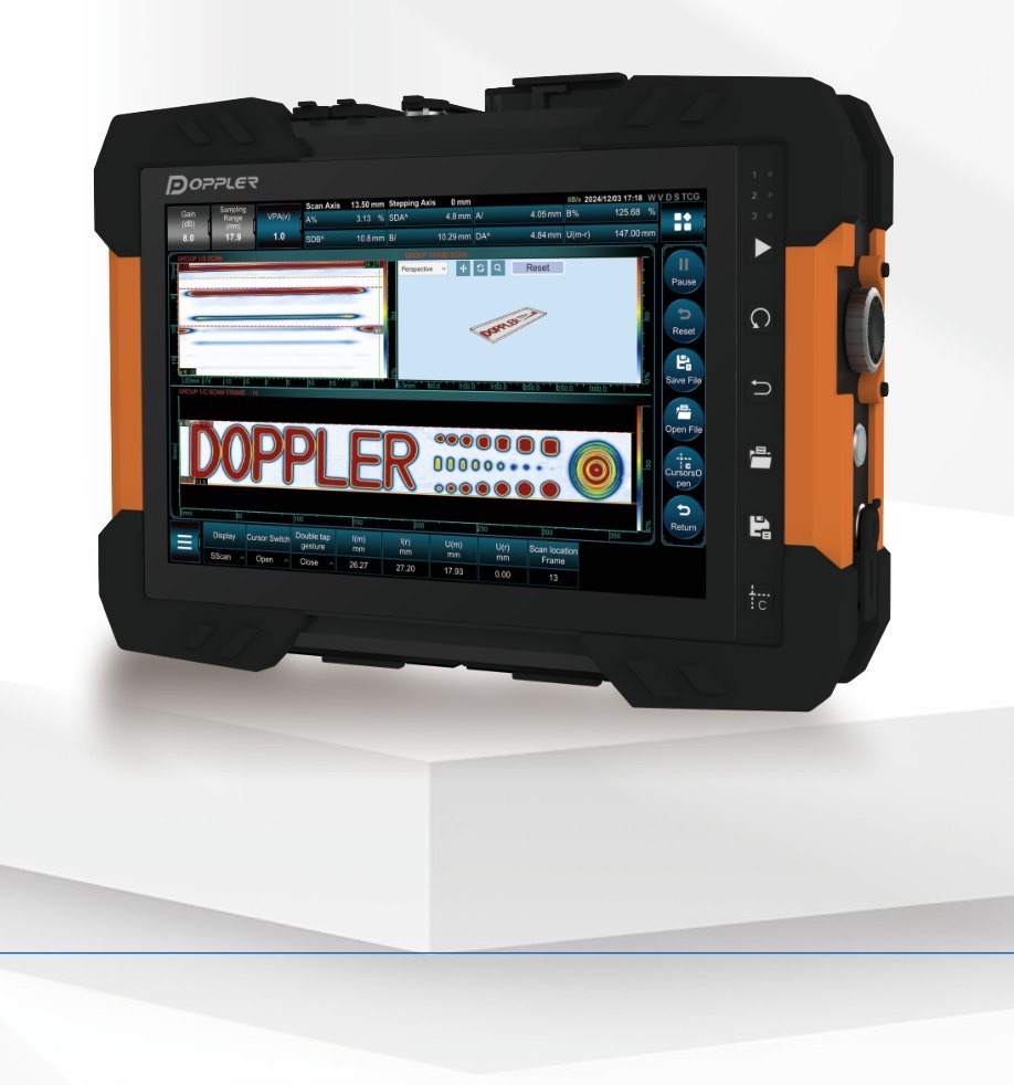
Upgraded Performance
200 V pulse voltage, 0.18–27 MHz ultra-wide bandwidth. More realistic signal reproduction.
Full Technology Integration
UT, TFM (FMC / PWI / 3D), PCI (FMC / PWI) and TOFD.
Real-Time Imaging & AIM
Real-time TFM with FMC data export. AIM sound field map for optimised setup and higher sensitivity.
Industrial-Grade Design
IP65 protection with WiFi and Bluetooth modules. Open architecture for in-house application development. Includes all functions of the V2 model.
NOVASCAN V3 — specifications
| Parameter | PA Module | Conventional UT |
|---|---|---|
| Configuration | ||
| Receive/Transmit | 64/128PR, 64/64PR, 32/128PR, 32/64PR | 2 / 2 |
| Velocity | 340–15240 m/s | 340–15240 m/s |
| Pulser | ||
| Test Mode | PE / PC / TT | PE / PC / TT / TOFD |
| Voltage | 10 V–200 V / 1 V step | 100 V / 200 V / 400 V |
| Pulse Shape | bipolar square wave / negative square wave | Negative Square Wave |
| Pulse Width | 20–1250 ns / 2.5 ns | 25–1000 ns / 2.5 ns |
| Rise Time | <10 ns | <10 ns |
| PRF | 40 kHz | 24 kHz (12 kHz per channel) |
| Delay | 20 µs / 2.5 ns | 20 µs / 2.5 ns |
| Receiver | ||
| Gain | 0–120 dB | 0–120 dB |
| Bandwidth | 0.18–27 MHz | 0.2–30 MHz |
| Delay | 20 µs / 2.5 ns | 20 µs / 2.5 ns |
| Data Acquisition | ||
| Sampling Rate | 200 MHz | 200 MHz |
| ADC | 16 bit | 16 bit |
| Focus Type | True Depth/Sound Path/Projection/Focal Plane/Dynamic focus | nd. |
| Rectification Mode | FW / HW+ / HW− / RF | FW / HW+ / HW− / RF |
| Maximum A-scan | 16384 | 16384 |
| Scan/Display | ||
| Type | TFM/Linear/Sectorial/Compound scanning | nd. |
| Display Mode | A/B/S/D/C/TFM/3D/TopC/Band chart | A/B/C/Band chart |
| Unit | mm/inch | mm/inch |
| TCG | ||
| Point | 16 | 16 |
| Gain Range | −24~40 dB | −24~40 dB |
| Max Gain Slope | 40 dB/10 ns | 40 dB/µs |
| Parameter | PA Module |
|---|---|
| Gate | |
| Number | Unlimited |
| Threshold | 0–100% |
| Report | |
| Format | WORD, PDF, EXCEL |
| Data Storage | |
| ROM | flash drive / built-in SSD 1 TB |
| Display Screen | |
| Size | 12.1 inch |
| Resolution | 1280 × 800 px |
| Type | Industrial TFT LCD Touch Screen |
| I/O Port | |
| USB | 2 × USB 3.1 + 1 × USB 2.0 |
| Ethernet | 1 × 1000 Mb/s |
| Video Output | HDMI |
| Encoder | LEMO 16-pin, supports up to three axes |
| Language | |
| Supported | English/Russian/French/German/Italian |
| Power Supply | |
| DC Supply Voltage | 15 V DC |
| Battery Type | lithium 10.8 V / 97.2 Wh (hot-swappable) |
| Continuous Working Time | about 5 hours |
| Case | |
| Size | 367 × 259 × 129 mm |
| Weight | 5.1 kg (battery excluded) 5.6 kg (including single battery) 6.1 kg (including dual batteries) |
| IP level | |
| IP | IP65 |
Applications
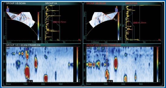
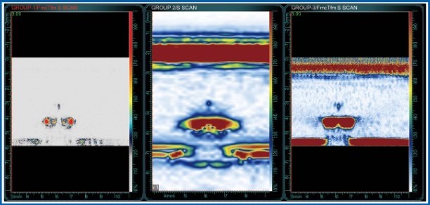

Phased Array Ultrasonic Detector
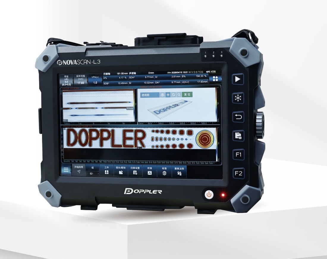
Lightweight & Portable
Only 2.7 kg — ideal for working at height, confined spaces and outdoor inspections.
Cost-Effective Performance
Delivers professional inspection capability at a competitive cost.
High-Speed & Accurate
PRF up to 20 kHz for efficient scanning. 0.5–20 MHz bandwidth. 800% A-scan display height.
Multi-Mode in One Unit
Integrated PA, UT, FMC-TFM and TOFD modes. Suitable for weld inspection, thickness measurement and flaw detection.
NOVASCAN L3 — specifications
| Parameter | PA Module | Conventional UT |
|---|---|---|
| Configuration | ||
| Receive/Transmit | 32/64PR, 16/64PR | 1 / 1 |
| Velocity | 340–15240 m/s | 340–15240 m/s |
| Pulser | ||
| Test Mode | PE / PC / TT | PE / PC / TT / TOFD |
| Voltage | 10 V–100 V / 1 V step | 100 V / 200 V / 400 V |
| Pulse Shape | Negative Square Wave | Negative Square Wave |
| Pulse Width | 20–1000 ns / 2.5 ns | 30–1000 ns / 2.5 ns |
| Rise Time | <4 ns | <8 ns |
| PRF | 20 kHz | 10 kHz |
| Delay | 20 µs / 2.5 ns | 20 µs / 2.5 ns |
| Receiver | ||
| Gain | 0–120 dB | 0–120 dB |
| Bandwidth | 0.5–20 MHz | 0.5–20 MHz |
| Delay | 20 µs / 2.5 ns | 20 µs / 2.5 ns |
| Data Acquisition | ||
| Sampling Rate | 100 MHz | 100 MHz |
| ADC | 16 bit | 14 bit |
| Focus Type | True Depth/Sound Path/Projection/Focal Plane/Dynamic focus | nd. |
| Rectification Mode | FW / HW+ / HW− / RF | FW / HW+ / HW− / RF |
| Maximum A-scan | 16384 | 16384 |
| Scan/Display | ||
| Type | TFM/Linear/Sectorial/Compound scanning | nd. |
| Display Mode | A/B/S/D/C/TFM/3D/TopC/Band chart | A/B/C/Band chart |
| Unit | mm/inch | mm/inch |
| TCG | ||
| Point | 16 | 16 |
| Gain Range | −18~40 dB | −18~40 dB |
| Max Gain Slope | 40 dB/10 ns | 40 dB/µs |
| Parameter | PA Module |
|---|---|
| Gate | |
| Number | A/B/C/I + Custom Gate |
| Threshold | 0–100% |
| Report | |
| Format | WORD, PDF, EXCEL |
| Display Screen | |
| Size | 10.1 inch |
| Resolution | 1920 × 1200 px |
| Type | Industrial TFT LCD Touch Screen |
| I/O Port | |
| USB | 2 × USB 3.0 |
| Ethernet | 1 × 1000 Mb/s |
| Video Output | HDMI 1.4b |
| Encoder | LEMO 16-pin |
| Language | |
| Supported | English/Russian/French/German/Italian |
| Power Supply | |
| DC Supply Voltage | 15 V DC |
| Battery Type | lithium 10.8 V / 97.2 Wh |
| Continuous Working Time | about 4 hours |
| Case | |
| Size | 302 × 228 × 96 mm |
| Weight | 2.7 kg (battery excluded) 3.2 kg (including single battery) |
| IP level | |
| IP | IP65 |
Applications
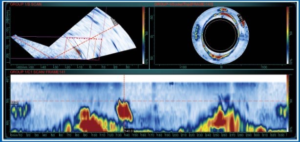
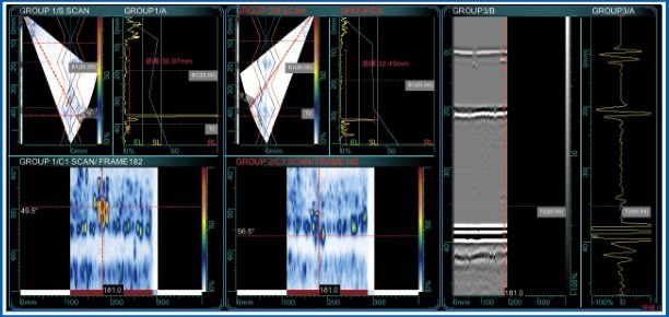

Phased Array Ultrasonic Detector
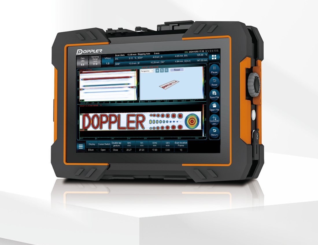
Upgraded Performance & Easy Operation
Higher pulse voltage, wider bandwidth and faster sampling; optimised UI for efficient workflow.
High-Speed Acquisition
128 channels · 40 kHz PRF · real-time processing · high precision.
Multi-Modal Inspection
FMC/TFM · PWI/TFM · PAUT · UT · TOFD — one platform for all scenarios.
3D Imaging & Smart Analysis
3D TFM with matrix probes · intelligent flaw recognition · high-capacity memory · fast data processing engine.
NOVASCAN V2 — specifications
| Parameter | PA Module | Conventional UT |
|---|---|---|
| Configuration | ||
| Receive/Transmit | 64/128PR, 64/64PR, 32/128PR, 32/64PR | 2 / 2 |
| Velocity | 340–15240 m/s | 340–15240 m/s |
| Pulser | ||
| Test Mode | PE / PC / TT | PE / PC / TT / TOFD |
| Voltage | 20 V–120 V / 10 V step | 100 V / 200 V / 400 V |
| Pulse Shape | Bipolar Square Wave | Negative Square Wave |
| Pulse Width | 20–1250 ns / 2.5 ns | 25–1000 ns / 2.5 ns |
| Rise Time | <10 ns | <10 ns |
| PRF | 40 kHz | 24 kHz (12 kHz per channel) |
| Delay | 20 µs / 2.5 ns | 20 µs / 2.5 ns |
| Receiver | ||
| Gain | 0–120 dB | 0–120 dB |
| Bandwidth | 0.3–25 MHz | 0.3–25 MHz |
| Delay | 20 µs / 2.5 ns | 20 µs / 2.5 ns |
| Data Acquisition | ||
| Sampling Rate | 200 MHz | 200 MHz |
| ADC | 16 bit | 16 bit |
| Focus Type | True Depth/Sound Path/Projection/Focal Plane/Dynamic focus | nd. |
| Rectification Mode | FW / HW+ / HW− / RF | FW / HW+ / HW− / RF |
| Maximum A-scan | 16384 | 16384 |
| Scan/Display | ||
| Type | TFM/Linear/Sectorial/Compound scanning | nd. |
| Display Mode | A/B/S/D/C/FMC-TFM/PWI-TFM/3D/TopC/Band chart | A/B/C/Band chart |
| Unit | mm/inch | mm/inch |
| Parameter | PA Module | Conventional UT |
|---|---|---|
| TCG | ||
| Point | 16 | 16 |
| Gain Range | −18~40 dB | −18~40 dB |
| Max Gain Slope | 40 dB/10 ns | 40 dB/µs |
| Parameter | PA Module |
|---|---|
| Gate | |
| Gate | A/B/C/I + Custom Gate |
| Threshold | 0~100% |
| TFM | |
| Point | 1024 × 1024 |
| Report | |
| Format | WORD, PDF, EXCEL |
| Data Storage | |
| ROM | EMMC (128 GB) + SSD (max. 1 TB) |
| Display Screen | |
| Size | 12.1 inch |
| Resolution | 1280 × 800 px |
| Type | Industrial TFT LCD Touch Screen |
| I/O Port | |
| USB | 2 × USB 3.0 + 1 × USB 2.0 |
| Ethernet | 1 × 1000 Mb/s |
| Video Output | HDMI |
| Encoder | LEMO 16-pin |
| Multifunctional Interface | LEMO 14-pin |
| Language | |
| Supported | English/Russian/French/German/Italian |
| Power Supply | |
| DC Supply Voltage | 15 V DC |
| Battery Type | lithium 10.8 V / 97.2 Wh (hot-swappable) |
| Continuous Working Time | about 5 hours |
| Case | |
| Size | 367 × 259 × 129 mm |
| Weight | 4.9 kg (battery excluded) 5.4 kg (including single battery) 5.9 kg (including dual batteries) |
| IP level | |
| IP | IP65 |
Applications
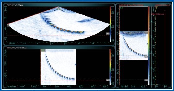
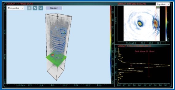

Phased Array Ultrasonic Detector
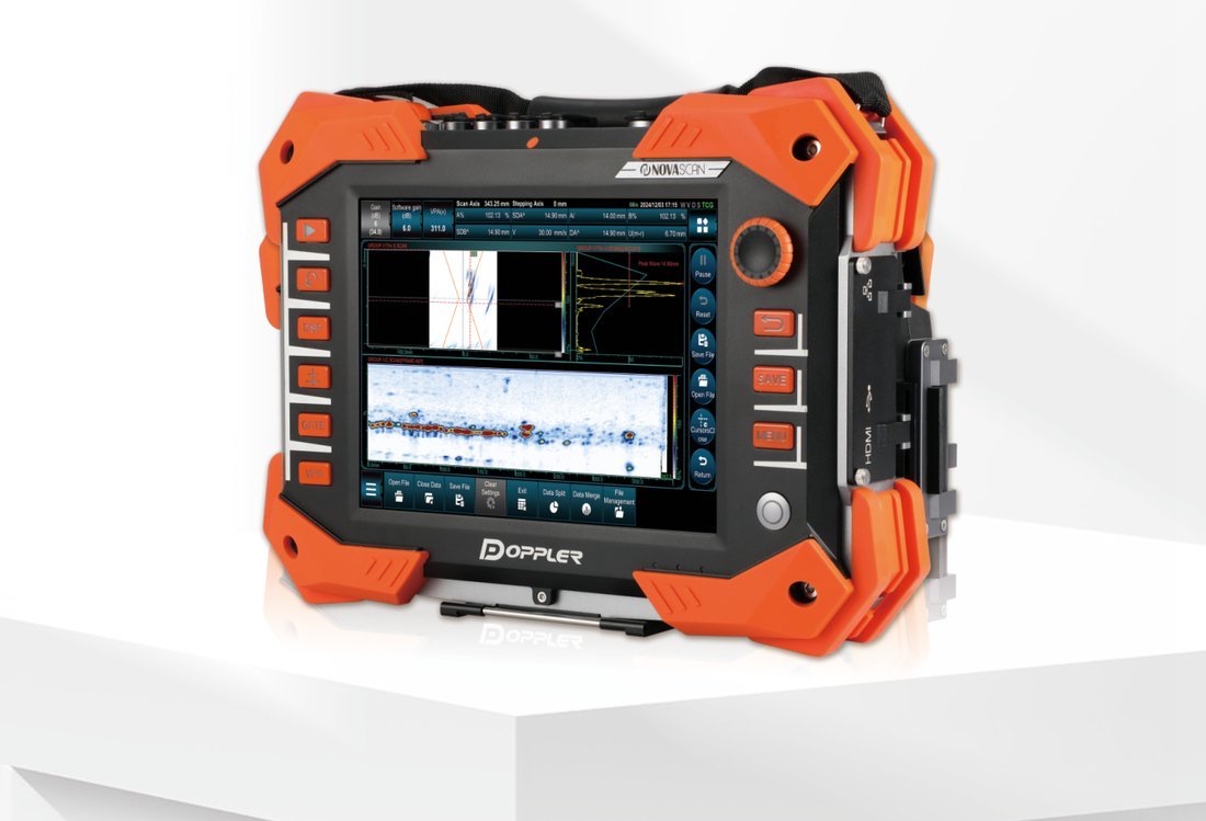
Multi-Mode Real-Time Imaging
FMC-TFM · PWI-TFM (real-time) · PA · dual-channel simultaneous TOFD/UT detection.
Full-Scene Adaptation
Linear and matrix arrays · corrosion · welds · pipelines · tanks · software upgradeable.
Simulation & Intelligent Analysis
3D simulation · real-time cross-section update when inspecting nozzles · setup wizard · AI recognition of joint flaws and corrosion.
Industrial-Grade Design
IP65 aluminium housing · −10 °C to 45 °C · dual batteries · 5 h continuous operation.
NOVASCAN V1 — specifications
| Parameter | PA Module | Conventional UT |
|---|---|---|
| Configuration | ||
| Receive/Transmit | 32/128PR, 32/64PR, 16/128PR, 16/64PR | 2 / 2 |
| Velocity | 340–15240 m/s | 340–15240 m/s |
| Pulser | ||
| Test Mode | PE / PC / TT | PE / PC / TT / TOFD |
| Voltage | 50 V / 100 V | 100 V / 200 V / 400 V |
| Pulse Shape | Negative Square Wave | Negative Square Wave |
| Pulse Width | 30–1000 ns / 2.5 ns | 30–1000 ns / 2.5 ns |
| Rise Time | <8 ns | <8 ns |
| PRF | 40 kHz | 24 kHz (12 kHz per channel) |
| Delay | 20 µs / 2.5 ns | 20 µs / 2.5 ns |
| Receiver | ||
| Gain | 0–110 dB | 0–110 dB |
| Bandwidth | 0.5–20 MHz | 0.5–20 MHz |
| Delay | 20 µs / 2.5 ns | 20 µs / 2.5 ns |
| Data Acquisition | ||
| Sampling Rate | 100 MHz | 100 MHz |
| No. of Focal Laws | 512 | nd. |
| Focus Type | True Depth/Sound Path/Projection/Focal Plane | nd. |
| Rectification Mode | FW / HW+ / HW− / RF | FW / HW+ / HW− / RF |
| Maximum A-scan | 16384 | 16384 |
| Scan/Display | ||
| Type | Linear/sector scan/compound scan/TFM | nd. |
| Display Mode | A/B/C/D/S/3D/TFM/TopC/Band chart | A/B/C/Band chart |
| Unit | mm/inch | mm/inch |
| Parameter | PA Module |
|---|---|
| IP level | |
| IP | IP65 |
| Parameter | PA Module | Conventional UT |
|---|---|---|
| TCG | ||
| Point | 16 | 16 |
| Gain Range | 40 dB | 40 dB |
| Max Gain Slope | 40 dB/µs | 40 dB/µs |
| Parameter | PA Module |
|---|---|
| Report | |
| Format | WORD, PDF, EXCEL |
| Data Storage | |
| ROM | flash drive / SSD (128 GB) |
| Single File Size | 4 GB |
| Display Screen | |
| Size | 10.4 inch |
| Resolution | 1024 × 768 px |
| Visible Area | 211 × 158 mm |
| Type | Industrial IPS capacitive touch screen |
| I/O Port | |
| USB | 2 |
| Ethernet | 1 × 1000 Mb/s |
| WiFi | supports USB external WiFi module (customisable) |
| Video Output | HDMI 1.4b |
| Encoder | LEMO 16-pin |
| Language | |
| Supported | Chinese/English/French/German/Russian/Italian |
| Power Supply | |
| DC Supply Voltage | 15 V DC |
| Battery Type | lithium 11.25 V / 99.6 Wh |
| Continuous Working Time | about 5 hours |
| Case | |
| Size | 360 × 260 × 130 mm |
| Weight | 6 kg (battery excluded) 6.5 kg (including single battery) 7 kg (including dual batteries) |
Applications
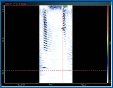
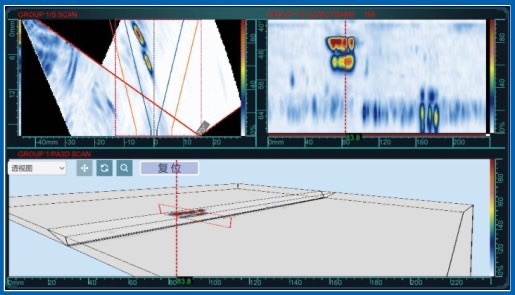

Portable Phased Array Flaw Detector
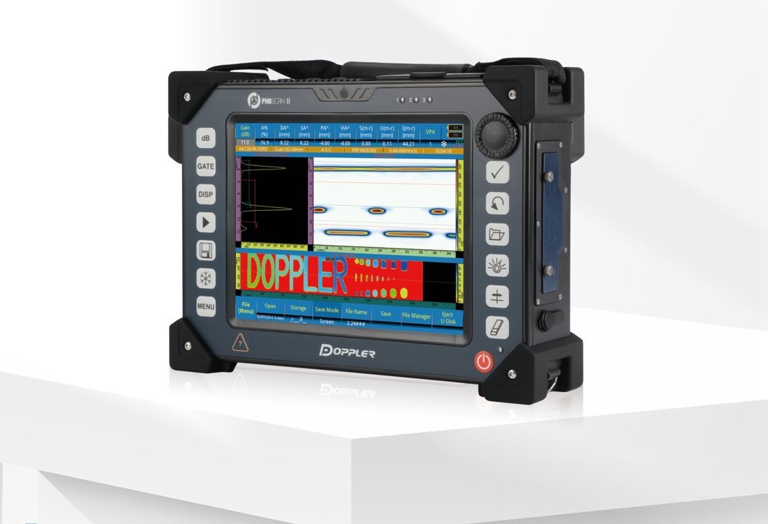
Advanced scanning
Dual-axis scanning · 3D simulation · precise multi-touch control.
Full probe compatibility
Wide 0.5–20 MHz bandwidth · DLA and DMA probes · customised solutions for metallic and non-metallic materials.
High-speed 64/128 architecture
Multi-channel parallel processing · ultra-fast synchronous acquisition · optimised for thick and highly attenuating materials.
Dynamic depth focusing (DDF)
High resolution across the full depth · better signal-to-noise ratio · clear imaging of welds and composite laminates.
PHASCAN II — specifications
| Parameter | PA Module | Conventional UT |
|---|---|---|
| Configuration | ||
| Receiver / Pulser | 64/128PR, 64/64P, 32/128PR, 32/64PR, 16/128PR, 16/64PR | 2 / 2 |
| Velocity | 635–15240 m/s | 635–15240 m/s |
| Pulser | ||
| Test Mode | PE / PC | PE / PC / TT / TOFD |
| Voltage | 50 / 100 V | 100 V / 200 V / 400 V |
| Pulse Shape | Negative Square Wave | Negative Square Wave |
| Pulse Width | 30–500 ns | 30–500 ns |
| Rise Time | <8 ns | <8 ns |
| PRF | 20 kHz | 11 kHz |
| Delay | 10 µs / 2.5 ns | 10 µs / 2.5 ns |
| Receiver | ||
| Gain | 0–80 dB | 0–110 dB |
| Bandwidth | 0.6–20 MHz | 0.5–20 MHz |
| Delay | 10 µs / 2.5 ns | 10 µs / 2.5 ns |
| Data Acquisition | ||
| Sampling Rate | 100 MHz | 100 MHz |
| Maximum A-scan | 32768 | 32768 |
| No. of Focal Laws | 1024 | nd. |
| Focus Type | True Depth/Sound Path/Projection/Focal Plane | nd. |
| Scan/Display | ||
| Type | Linear/Sectorial | nd. |
| Display Mode | A/B/C/S scans | A/B/C |
| Unit | mm/inch | mm/inch |
| Parameter | PA Module |
|---|---|
| TCG | |
| Point | 16 |
| Gain Range | 40 dB |
| Max Gain Slope | 40 dB/µs |
| Parameter | PA Module |
|---|---|
| Report | |
| Format | HTML |
| Data Storage | |
| Removable storage | flash drive / SD card / built-in SSD |
| Display Screen | |
| Size | 10.4 inch |
| Resolution | 800 × 600 px |
| Type | Industrial TFT LCD capacitive touch screen |
| I/O Port | |
| USB | 3 |
| Ethernet | 1000 Mb/s |
| Video Output | DVI / HDMI |
| Encoder | DB15; dual-axis |
| Language | |
| Supported | Chinese/English/Russian |
| Power Supply | |
| DC Supply Voltage | 15 V DC |
| Battery Type | lithium (hot-swappable) |
| Continuous Working Time | about 5 hours |
| Case | |
| Size | 325 × 230 × 130 mm |
| Weight | 5 kg (battery excluded) 5.5 kg (including single battery) 6 kg (including dual batteries) |
| Hardware | |
| CPU | 4 × 1.2 GHz |
| File system | FAT32 / NTFS |
| Storage capacity | 128 GB |
| Software | |
| 2D C-scan / 3D beam simulation / matrix probes | supported |
| Model import / C-scan projection / real-time TKY loading | supported |
| Real-time 3D interface with multi-touch support | supported |
| Secondary development / online monitoring / single file size | supported / supported / 1 GB |
Applications
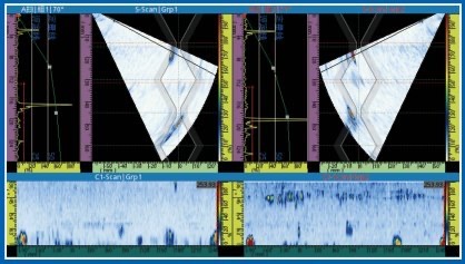
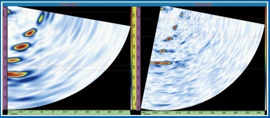
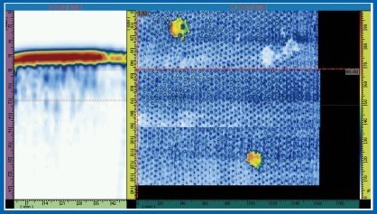

Portable Phased Array Flaw Detector
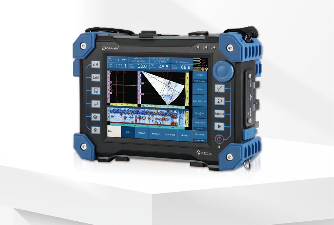
Compact multi-mode platform
PAUT · TOFD · UT · bolt inspection · 64 independent transmit channels · cost-effective all-in-one solution.
Dual-system architecture
Unique dual-engine "PAUT + bolts" design · fast mode switching · flexible response to varied tasks.
Lightweight and field-ready
3.5 kg construction · ideal for work at height, on masts and pipeline racks · high environmental resistance.
Intelligent operation and visualisation
Ready-made bolt inspection programs · one-button save and recall · real-time 3D imaging · colour coding of flaws.
FLEXSCAN — specifications
| Parameter | PA Module | Conventional UT |
|---|---|---|
| Configuration | ||
| Receive/Transmit | 32/64PR, 16/64PR | 1 / 2 |
| Velocity | 635–15240 m/s | 635–15240 m/s |
| Pulser | ||
| Test Mode | PE / PC | PE / PC / TT / TOFD |
| Voltage | 50 V / 100 V / 130 V | 100 V / 200 V / 400 V |
| Pulse Shape | Negative Square Wave | Negative Square Wave |
| Pulse Width | 30–500 ns | 30–500 ns |
| Rise Time | <8 ns | <8 ns |
| PRF | 20 kHz | 6 kHz |
| Delay | 10 µs / 2.5 ns | 10 µs / 2.5 ns |
| Focus Type | True Depth/Sound Path/Projection/Focal Plane | nd. |
| Receiver | ||
| Gain | 0–80 dB | 0–110 dB |
| Bandwidth | 0.6–18 MHz | 0.5–20 MHz |
| Delay | 10 µs / 2.5 ns | 10 µs / 2.5 ns |
| Scan/Display | ||
| Type | Linear/Sectorial | nd. |
| Display Mode | A/B/C/S scans | A/B |
| Unit | mm/inch | mm/inch |
| Parameter | PA Module |
|---|---|
| TCG | |
| Point | 16 |
| Gain Range | 40 dB |
| Max Gain Slope | 40 dB/µs |
| Parameter | PA Module |
|---|---|
| Report | |
| Format | Web |
| Data Storage | |
| Removable storage | flash drive / SD card |
| Display Screen | |
| Size | 8.4 inch |
| Resolution | 800 × 600 px |
| Type | Industrial TFT LCD Touch Screen |
| I/O Port | |
| USB | 2 |
| Network | 100 Mb/s |
| Video Output | HDMI |
| Encoder | LEMO 16-pin; single-axis |
| Language | |
| Supported | Chinese/English/Russian |
| Power Supply | |
| DC Supply Voltage | 15 V DC |
| Battery Type | lithium (hot-swappable) |
| Continuous Working Time | about 4 hours |
| Case | |
| Size | 296 × 209 × 89 mm |
| Weight | 3.6 kg (battery excluded) 4.1 kg (including single battery) |
ROBUST P series — phased array ultrasonic boards
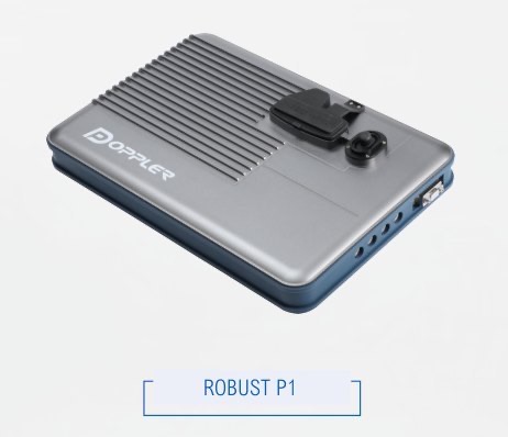
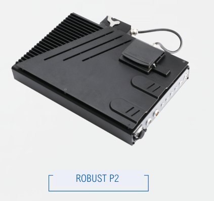
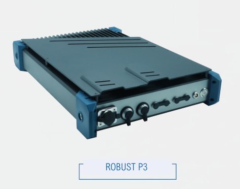
Model overview
| Model | Channel configuration | Pulse voltage | Bandwidth | A-scan amplitude |
|---|---|---|---|---|
| ROBUST P1 | 32/128 | 20–100 V / 10 V | 0.9–20 MHz | 200% |
| ROBUST P2 | 64/128 | 20–120 V / 10 V | 0.35–25 MHz | 800% |
| ROBUST P3 | 64/128 | 10–200 V / 1 V | 0.18–27 MHz | 1600% |
High-performance automated inspection platform
ROBUST P1/P2/P3 phased array boards · broad use in manufacturing, aerospace, transport and new energy · efficient quality control and production optimisation.
64-channel parallel expansion (P2/P3)
Parallel architecture · scanning 2–3× faster than conventional mode · higher throughput in demanding applications.
Flexible operating modes and SDK support
PA · UT · TFM (FMC/PWI/3D) · PCI · TOFD · free switching between TFM and PA · two independent TOFD channels (P2 and P3) · comprehensive SDK for fast system integration.
Scalable and customised solutions
Synchronous multi-channel inspection · suited to mass production and aerospace-grade testing · flexible solutions for complex automated tasks.
ROBUST P1 / P2 / P3 — specifications
| Parameter | P1 | P2 | P3 |
|---|---|---|---|
| Configuration | |||
| Receive/Transmit | 32/128PR, 32/64PR, 16/128PR, 16/64PR | 64/128PR, 64/64PR, 32/128PR, 32/64PR | 64/128PR, 64/64PR, 32/128PR, 32/64PR |
| Pulser | |||
| Test Mode | PE / PC / TT | PE / PC / TT | PE / PC / TT |
| Voltage | 20–100 V | 20 V–120 V / 10 V | 10 V–200 V / 1 V step |
| Pulse Shape | Negative Square Wave | Bipolar Square Wave | Bipolar Square Wave |
| Pulse Width | 25–1000 ns / 2.5 ns | 20–1250 ns / 2.5 ns | 20–1250 ns / 2.5 ns |
| Rise Time | <10 ns | <10 ns | <10 ns |
| PRF | 40 kHz | 40 kHz | 40 kHz |
| Delay | 20 µs / 2.5 ns | 20 µs / 2.5 ns | 20 µs / 2.5 ns |
| Receiver | |||
| Gain | 0–120 dB | 0–120 dB | 0–120 dB |
| Bandwidth | 0.9–20 MHz | 0.3–25 MHz | 0.18–27 MHz |
| Delay | 20 µs / 2.5 ns | 20 µs / 2.5 ns | 20 µs / 2.5 ns |
| Data Acquisition | |||
| Sampling Rate | 100 MHz | 200 MHz | 100 MHz / 200 MHz |
| No. of Focal Laws | 512 | 1024 | 1024 |
| ADC | 10 bit | 16 bit | 16 bit |
| Maximum A-scan | 16384 | 16384 | 16384 |
| Scan/Display | |||
| Test modes | PA / UT / TOFD / FMC-TFM / PWI-TFM / FMC-PCI / PWI-PCI | ||
| Type | TFM/Linear/Sectorial/Compound scanning | ||
| Display Mode | A / B / S / D / C / 3D / TFM / TopC / Band chart | ||
| Measurement units | mm/inch | ||
| Power Supply | |||
| DC | 15 V DC | 15 V DC | 15 V DC |
| Parameter | P1 | P2 | P3 |
|---|---|---|---|
| TFM | |||
| Point | 4096 × 1024 | 1024 × 1024 | 1024 × 1024 |
| TFM Aperture | 128 transmit | 128 transmit | 128 transmit |
| TFM modes | TT, TTT, TTTT, TTTTT, LL, LLL, LLLL, LLLLL, TLT, TLL, LTT, LLT | ||
| TCG | |||
| Point | 16 | 16 | 16 |
| Gain Range | 40 dB | −18~40 dB | −24~40 dB |
| Max Gain Slope | 40 dB/µs | 40 dB/10 ns | 40 dB/10 ns |
| Gate | |||
| Number | A/B/C/I + Custom | A/B/C/I + Custom | A/B/C/I + Custom |
| Threshold | 0–100% | 0–100% | 0–100% |
| Gate trigger mode | peak / edge | peak / edge | peak / edge |
| I/O Port | |||
| Ethernet | 1000 Mb/s | 1000 Mb/s | 1000 Mb/s |
| Encoder | LEMO 16-pin | dual-axis, LEMO 16-pin | dual-axis, LEMO 16-pin |
| Case | |||
| Size | 350 × 245 × 55 mm | 400 × 280 × 80 mm | 400 × 280 × 80 mm |
| Weight | 4 kg | 5 kg | 5 kg |
| Language | |||
| Supported | Chinese/English/French/German/Russian/Italian | ||
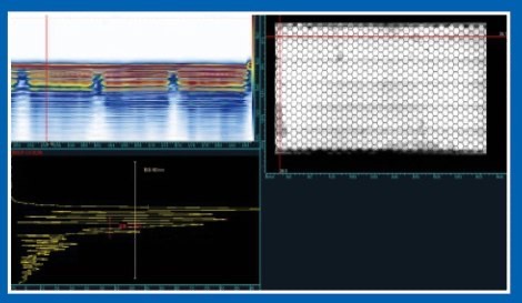
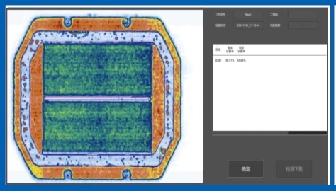
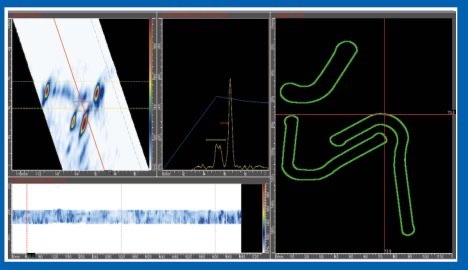
Applications
ROBUST M1 — multi-channel ultrasonic board
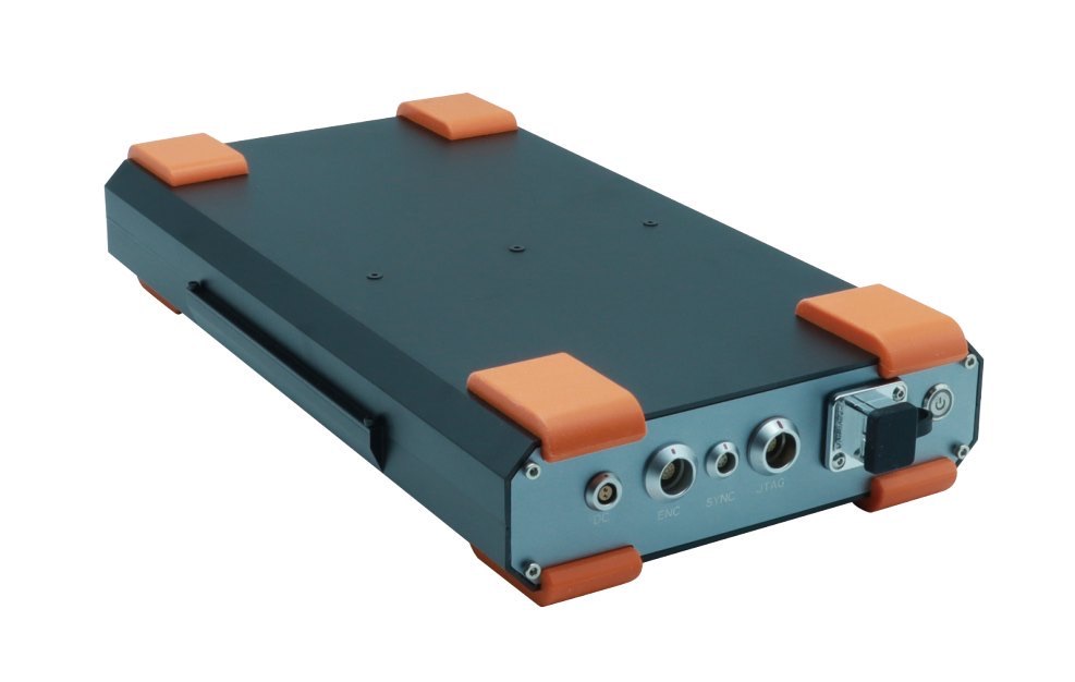
The ROBUST M1 multi-channel ultrasonic board uses an advanced modular design, offering standard 4- and 8-channel variants that can be flexibly expanded with further channels as required, so it meets individual inspection needs. Each channel supports independent parallel sampling, which gives high inspection throughput and precision and significantly improves overall reliability. The ROBUST M1 is used in industry, medicine, scientific research and other fields, providing accurate and reliable ultrasonic solutions for thickness measurement, flaw detection and other tasks.
Modular design and flexible expansion
The channel count can be matched to requirements and the system expanded to meet varied inspection needs.
Efficient parallel sampling technology
Each channel samples independently, which eliminates mutual interference and allows precise real-time inspection at high speed.
High inspection speed
Pulse repetition frequency support up to 96 kHz (max. 12 kHz for a single UT channel) — suited to automated applications with high precision and speed requirements.
Complete SDK and customisation services
SDK development kit and dedicated solutions supporting automated production lines and quality improvement.
ROBUST M1 — specifications
| Parameter | Value |
|---|---|
| Configuration | |
| Receive/Transmit | 4/4, 8/8 |
| Velocity | 340–15240 m/s |
| Pulser | |
| Test Mode | PE / PC / TT / TOFD |
| Voltage | 20 V–400 V, 10 V step |
| Pulse Shape | Negative Square Wave |
| Pulse Width | 25–1000 ns, 2.5 ns step |
| Rise Time | <8 ns |
| PRF | single channel up to 18 kHz, 4 channels up to 47 kHz, 8 channels up to 64 kHz |
| Delay | 20 µs / 2.5 ns |
| Receiver | |
| Gain | 0–120 dB |
| Bandwidth | 0.3–25 MHz |
| Delay | 20 µs / 2.5 ns |
| Data Acquisition | |
| Sampling Rate | 100 MHz |
| ADC | 12 bit |
| Maximum A-scan | 16384 |
| Rectification Mode | FW / HW+ / HW− / RF |
| Power Supply | |
| DC | 15 V DC |
| Parameter | Value |
|---|---|
| Scan/Display | |
| Display Mode | A / B / C / Band chart / FFT |
| Unit | mm/inch |
| DAC | |
| Point | 16 |
| TCG | |
| Point | 16 |
| Gain Range | 40 dB |
| Max Gain Slope | 40 dB/µs |
| Band Filter | |
| Band Filter | supported |
| Gate | |
| Gate | A/B/C/I + Custom Gate |
| Threshold | 0–100% |
| Gate trigger mode | peak / edge |
| Report | |
| Format | WORD, PDF, EXCEL |
| I/O Port | |
| Ethernet | 1000 Mb/s |
| Encoder | LEMO 16-pin |
| Case | |
| Size | 360.5 × 200 × 60.7 mm |
| Weight | 8 channels: 2.1 kg · 4 channels: 1.8 kg |
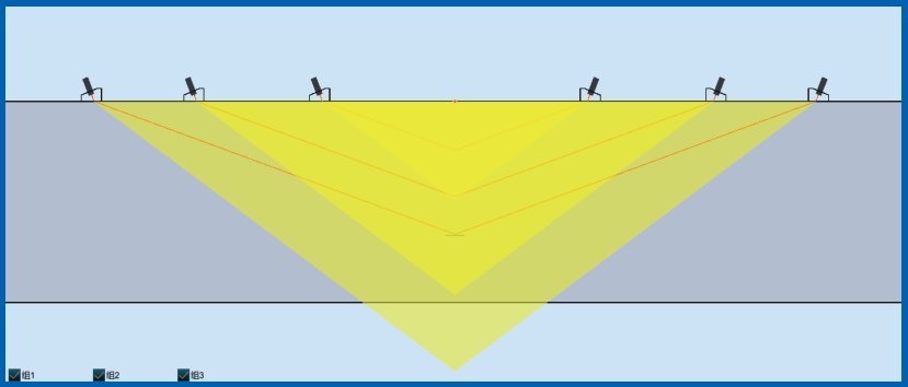
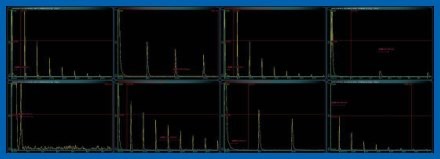
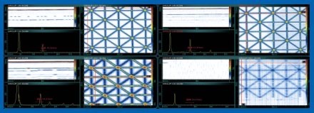
Software features
ROBUST S1 — single-channel ultrasonic board
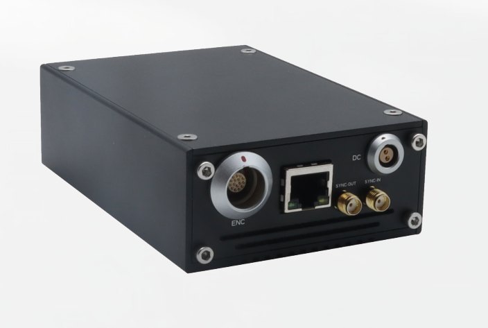
The ROBUST S1 single-channel ultrasonic board combines an excellent performance-to-price ratio, high reliability, fast integration and flexible expansion, precisely matching the needs of basic inspection, portable applications and automation — key requirements in many working scenarios. The product is widely used in aerospace material testing, non-destructive testing of automotive parts, biomedical ultrasound imaging and other fields. Whether for thickness measurement, flaw detection or other ultrasonic applications, it delivers accurate and dependable results.
Universal connectors
The highly universal interface supports many popular connector types. It connects easily to external devices — computers, sensors and displays — giving fast data transmission and exchange without complex switches, which saves time and cost.
Broadband inspection
The broadband characteristic allows signals to be captured and processed precisely across a wider frequency range. Whether for small flaws or complex analysis of material properties, it gives clear and dependable results, meeting the needs of different inspection scenarios.
High transmission voltage
Output voltage up to 400 V delivers high energy for ultrasonic testing. Even in complex conditions and demanding tasks it gives the ultrasonic signal sufficient strength and penetration, improving inspection sensitivity and reliability.
High modularity
Simple signal path
Easy operation and customisation
and dual-element probes
ROBUST S1 — specifications
| Parameter | Value |
|---|---|
| Configuration | |
| Receive/Transmit | 1/1 |
| Velocity | 340–15240 m/s |
| Pulser | |
| Test Mode | PE / PC / TT / TOFD |
| Voltage | 100 V / 200 V / 400 V |
| Pulse Shape | spike pulse / negative square wave |
| Pulse Width | 20–1000 ns, 2.5 ns step |
| Rise Time | <8 ns |
| PRF | 40 kHz |
| Receiver | |
| Gain | 0–110 dB |
| Bandwidth | 1–34.5 MHz |
| Data Acquisition | |
| Sampling Rate | 200 MHz |
| ADC | 16 bit |
| Maximum A-scan | 65535 |
| Rectification Mode | FW / HW+ / HW− / RF |
| Power Supply | |
| DC | 15 V DC |
| Parameter | Value |
|---|---|
| Scan/Display | |
| Display Mode | A / B / C / Band chart / FFT |
| Unit | mm/inch |
| TCG | |
| Point | 32 |
| Gain Range | 40 dB |
| Max Gain Slope | 40 dB/µs |
| Gate | |
| Gate | A/B/C/I + Custom Gate |
| Threshold | 0–100% |
| Gate Mode | depth / sound path |
| I/O Port | |
| Ethernet | 1000 Mb/s |
| Encoder | dual-axis, LEMO 16-pin |
| Synchronisation connector | SMA |
| Case | |
| Size | 120 × 90 × 40 mm |
| Weight | 0.4 kg |
Applications
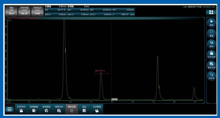
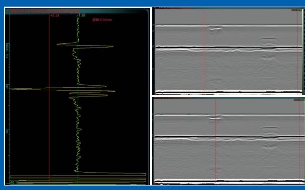
ROBUST F1 — phased array ultrasonic board
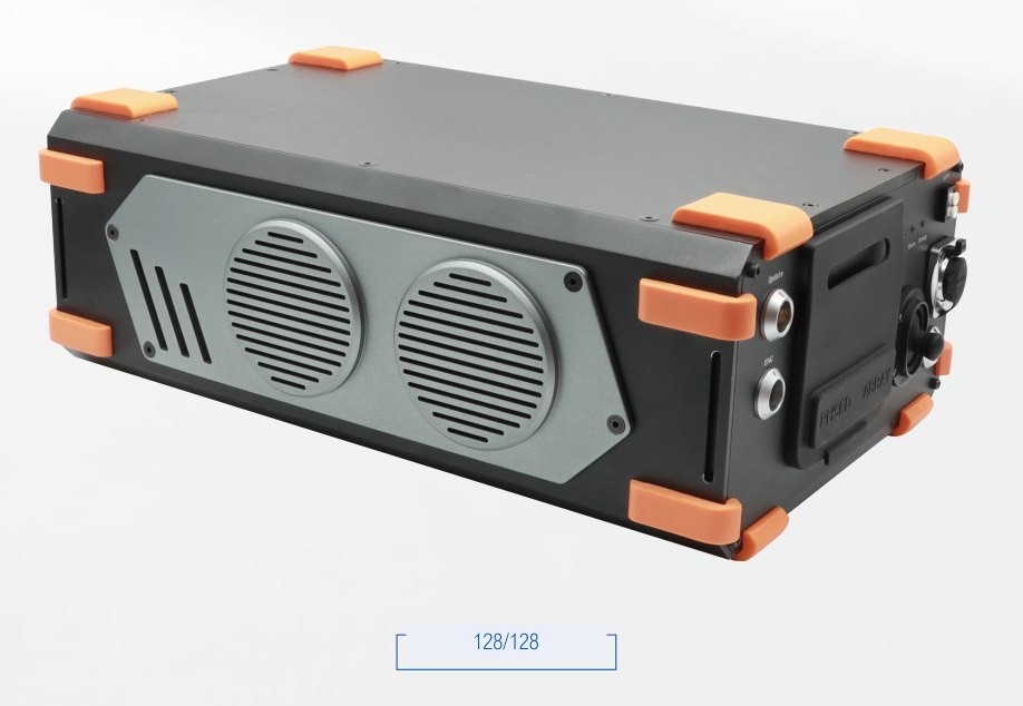
High-performance matrix probe platform
Fast processing architecture · 64/64 · 128/128 · 256/256 versions · optimised for matrix and MA probes · ideal for nuclear power, aerospace, railways and power generation · suited to thick, highly attenuating and dissimilar-metal welds.
Parallel scanning and ultra-fast acquisition
Parallel multi-transducer scanning · multi-cycle excitation · PRF up to 40 kHz · multi-channel real-time processing.
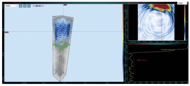
3D TFM and very high resolution
3D, FMC-TFM, PWI-TFM, FMC-PCI and PWI-PCI modes · up to 4 million data points · high-resolution imaging for complex structures.
High-energy pulse and technology integration
Bipolar pulse with high penetration · PA-UT · PA-TOFD combination · suited to different probes and difficult working conditions.
ROBUST F1 — specifications
| Parameter | Value |
|---|---|
| Configuration | |
| Receive/Transmit | 64/64, 128/128, 256/256 |
| Velocity | 340–15240 m/s |
| Pulser | |
| Test Mode | PE / PC / TT |
| Voltage | 128: 40 V/70 V/100 V/130 V/150 V 256: 40 V/70 V/100 V/130 V/150 V/200 V |
| Pulse Shape | Bipolar Square Wave |
| Pulse Width | 20–1000 ns, 2.5 ns step |
| Rise Time | <10 ns |
| PRF | 40 kHz |
| Delay | 20 µs / 2.5 ns |
| Receiver | |
| Gain | 0–120 dB |
| Bandwidth | 0.4–25 MHz |
| Delay | 20 µs / 2.5 ns |
| Data Acquisition | |
| Sampling Rate | 200 MHz |
| ADC | 16 bit |
| Maximum A-scan | 16384 |
| No. of Focal Laws | 1024 |
| Focus Type | True Depth/Sound Path/Projection/Focal Plane |
| Rectification Mode | FW / HW+ / HW− / RF |
| Parameter | Value |
|---|---|
| Scan/Display | |
| Type | TFM/Linear/Sectorial/Compound scanning |
| Display Mode | A/B/S/D/C/TFM/3D/TopC/Band chart |
| Unit | mm, inch |
| Language | |
| Supported | Chinese/English/French/German/Russian/Italian |
| TCG | |
| Point | 16 |
| Gain Range | 40 dB |
| Band Filter | |
| Band Filter | full-time data averaging |
| Gate | |
| Gate | A/B/C/I + Custom Gate |
| Threshold | 0–100% |
| Gate trigger mode | peak / edge |
| I/O Port | |
| Ethernet | 1000 Mb/s, 10 Gb/s |
| Encoder | dual-axis, LEMO 16-pin |
| Physical specification | |
| Size | 388.53 × 243 × 137 mm |
| Weight | 7 kg |
Applications
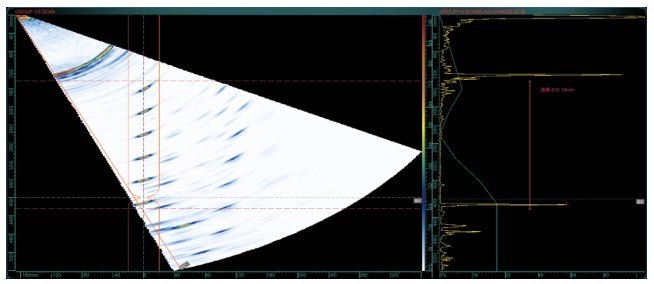
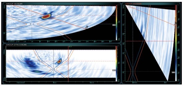
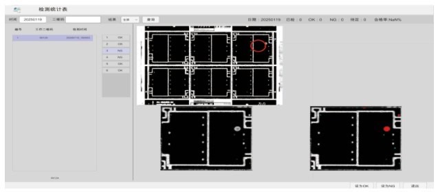
ROBUST L1 — compact phased array ultrasonic board
In precision industrial testing, instrument miniaturisation and a favourable performance-to-price ratio are becoming the new user expectation. In non-destructive testing for aerospace, power generation and rail transport, the requirements for handiness and economy are especially high in field work and confined spaces. The new ROBUST L1 series (16/128 boards) from Guangzhou Doppler is an efficient and economical answer to those needs.
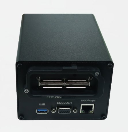
Small size — always at hand
The ROBUST L1 series has a compact design, small dimensions and low mass (approx. 1 kg), which makes it ideal for field inspection and system integration where space is limited — it is easy to mount and deploy.
Despite the compact dimensions, performance has not been cut back. The board inherits the ruggedness and reliability of the Doppler product line, performs in demanding industrial conditions and forms a durable foundation for the stability of the whole system.
Complete functionality and wide application
Although the ROBUST L1 is positioned as a lighter and more economical solution, its functionality remains complete. The board integrates three inspection modes — PA, TFM and PWI — flexibly meeting varied non-destructive testing requirements. It supports A/B/S/C/TFM/TopC presentations and combined modes, as well as full encoder data recording.
The board supports all kinds of automated phased array ultrasonic system platforms and provides extended hardware and software interfaces for in-house application development. This leaves room for future function customisation and system expansion.
An economical choice without compromising performance
The ROBUST L1 series uses a hardware architecture with 128 transmit and 16 receive channels. Cost has been reduced significantly while high performance is retained, and the board still delivers excellent characteristics in most typical inspection applications.
For companies and start-up teams with a limited budget that want to adopt advanced phased array technology, the L1 series is an excellent entry and expansion option.
ROBUST L1 — specifications
| Parameter | Value |
|---|---|
| Configuration | |
| Receive/Transmit | 16/128 |
| Velocity | 340–15240 m/s |
| Pulser | |
| Test Mode | PE / PC / TT |
| Voltage | 20 V–100 V / 10 V step |
| Pulse Shape | Negative Square Wave |
| Pulse Width | 30–1000 ns, 2.5 ns step |
| Rise Time | <10 ns |
| PRF | 20 kHz |
| Delay | 20 µs / 2.5 ns |
| Receiver | |
| Gain | 0–120 dB |
| Bandwidth | 0.5–20 MHz |
| Data Acquisition | |
| Sampling Rate | 100 MHz |
| ADC | 12 bit |
| Wave Height | 200% |
| Maximum A-scan | 16384 |
| No. of Focal Laws | 1024 |
| Focus Type | True Depth/Sound Path/Projection/Focal Plane |
| Rectification Mode | FW / HW+ / HW− / RF |
| Power Supply | |
| DC | 12 V DC |
| Parameter | Value |
|---|---|
| Scan/Display | |
| Type | TFM/Linear/Sectorial/Compound scanning |
| Display Mode | A/B/S/D/C/3D/TFM/TopC/Band chart |
| Unit | mm/inch |
| TCG | |
| Point | 16 |
| Gain Range | 40 dB |
| Max Gain Slope | 40 dB/ns |
| Gate | |
| Gate | A/B/C/I + Custom Gate |
| Threshold | 0–100% |
| Gate Mode | peak / edge |
| I/O Port | |
| Ethernet | 1000 Mb/s |
| Encoder | dual-axis, DB15 |
| Language | |
| Supported | Chinese/English/Russian/French/Italian/German |
| Case | |
| Size | 152 × 116 × 87 mm |
| Weight | 1 kg |
Applications
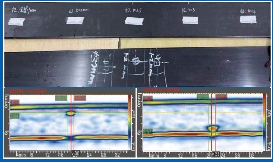
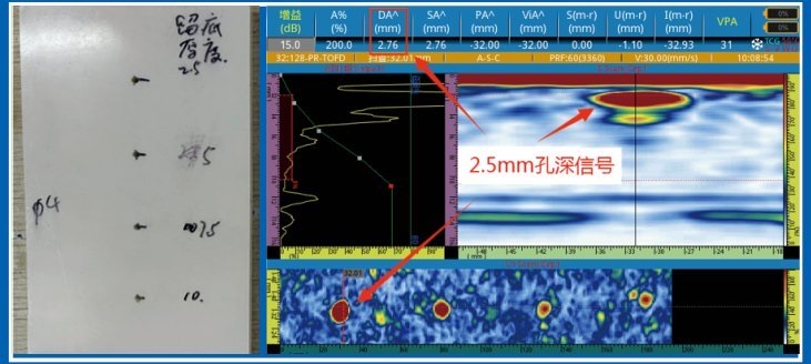
Nexus F1 — pulser-receiver
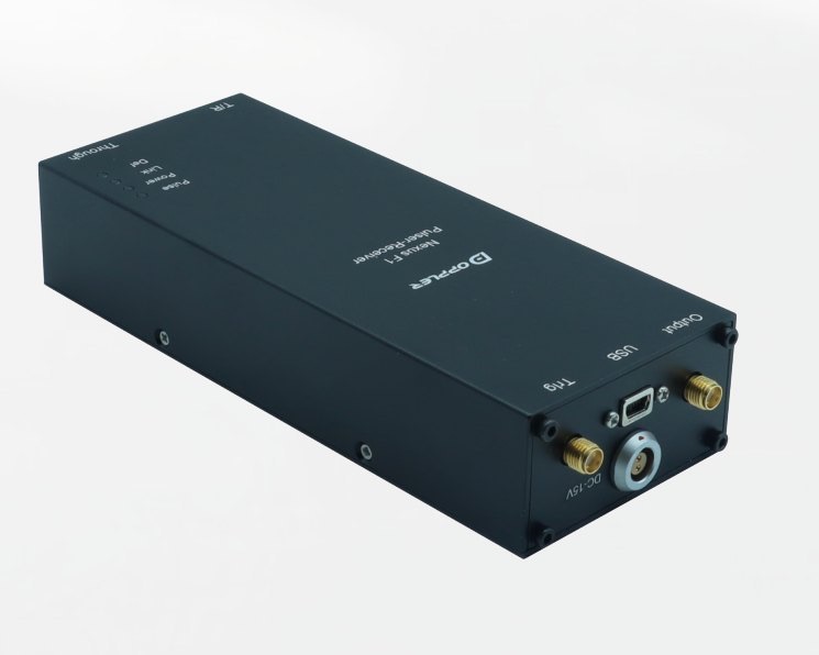
The Nexus F1 pulser-receiver is a new generation of high-performance ultrasonic transmit-receive units, developed and manufactured in-house by Doppler. It was designed specifically for high-frequency ultrasonic systems. Its key role is to provide technical support for material flaw detection through precise control of transmission and echo resolution of ultrasonic signals.
Features
- Compact, low-power design — small size, easy integration.
- Two operating modes: T/R echo (one probe) · through-transmission (two probes).
- Flexible filtering: selectable high-pass and low-pass filters.
- Broadband reception: adjustable bandwidth 1–150 MHz.
- High-speed operation: PRF up to 70 kHz for automated lines.
Efficient and flexible, the Nexus F1 excels in high-frequency ultrasonic testing.
Parameter comparison
| Model / parameters | Transmit/receive bandwidth (MHz) | Gain Range (dB) | Minimum step (dB) | Max. PRF (kHz) | High-pass filter (MHz) | Low-pass filter (MHz) | Excitation time (ns) | Sampling frequency (GHz) |
|---|---|---|---|---|---|---|---|---|
| Domestic version | 1–150 | −12~70 | 0.5 | 70 | 1/10 | 65/150 | 3.4 | 2 |
| Imported version | 5~300 | −11~70 | 0.5 | 65 | 5/30 | 150/300 | 2.2 | 2 |
Nexus F1 — specifications
| Parameter | Value |
|---|---|
| Receiver | |
| Test Mode | T/R echo, through-transmission |
| Bandwidth | 1 ~ 150 MHz |
| Gain Range | −12 ~ 70 dB |
| High-pass filter (MHz) | 1, 10 |
| Low-pass filter (MHz) | 75, 175 |
| Pulser | |
| Pulse Shape | spike pulse |
| Pulse falling edge | <3.4 ns |
| Voltage | 50 V–150 V |
| PRF | 70 kHz |
| Parameter | Value |
|---|---|
| I/O Port | |
| Communication interface | Mini USB 2.0 |
| Trig input | SMA coaxial connector |
| Output | SMA coaxial connector |
| Probe connector | SMA coaxial connector |
| Power Supply | |
| DC Supply Voltage | 15 V DC |
| Case | |
| Size | 165.6 × 61.4 × 30.49 mm |
| Weight | 0.265 kg |
Applications
As a precision acoustic device suited to many working scenarios, high-frequency ultrasonic pulser-receivers have a broad and steadily expanding field of application covering industry, medicine, materials engineering and bioengineering.
- Industrial inspection: material defect identification and precision manufacturing
- 3C industry: weld defects in liquid-cooled heat sinks; quality of titanium-aluminium alloys.
- Microelectronic components: ceramic capacitors, ceramic copper-clad boards, internal cracks in wafers and micro-scale imaging of delamination in integrated circuit packages.
- Assessment of special materials and complex structures, including coating delamination on turbine blades.
- Medicine: high-resolution surface imaging and therapy monitoring
- Materials engineering: microstructure characterisation and stress analysis
- Acoustic microscopy and nanoscale imaging: grain orientation and grain-boundary stress analysis.
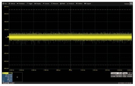
Noise, receiver and transmit waveform characteristics
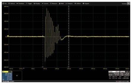
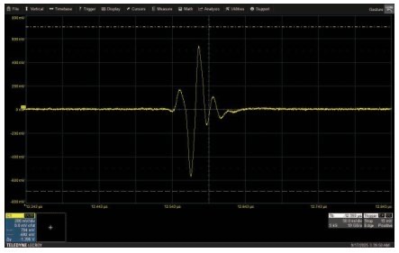
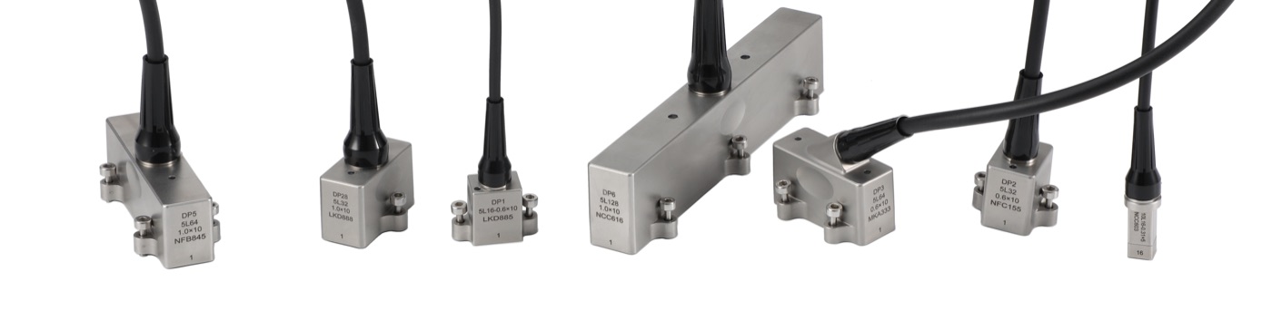
Linear Array Probe Series
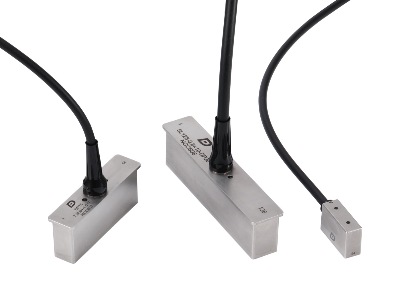
Linear probes are currently the most widely used type of phased array probe. Combined with a wedge they allow shear or longitudinal wave inspection and are widely used to inspect the parent material and welded joints of pipe fittings, forgings and plates.
Acoustic matching
Acoustically matched with Rexolite.
Versatility
Shear or longitudinal wave inspection combined with a wedge — parent material and welds of pipe fittings, forgings and plates.
Applications and custom versions
Aerospace, oil pipelines, automobile axles and more. Special probes can be customised for non-standard applications.
Linear array probes — specifications
| Model | Frequency (MHz) | Elements | Pitch (mm) | Active Aperture (mm) | Elevation (mm) | Long (mm) | Width (mm) | Height (mm) | Case Type |
|---|---|---|---|---|---|---|---|---|---|
| 10L16-0.2×5 | 10 | 16 | 0.2 | 3.2 | 5 | 6 | 8 | 23 | DP40 |
| 10L16-0.31×5 | 10 | 16 | 0.31 | 4.96 | 5 | 8 | 8 | 21 | DP30 |
| 5L16-0.6×10 | 5 | 16 | 0.6 | 9.6 | 10 | 13.4 | 28.5 | 20 | DP1 |
| 7.5L16-0.6×10 | 7.5 | 16 | 0.6 | 9.6 | 10 | 13.4 | 28.5 | 20 | DP1 |
| 7.5L32-0.3×10 | 5 | 32 | 0.3 | 9.6 | 10 | 13.4 | 28.5 | 20 | DP1 |
| 10L32-0.3×10 | 10 | 32 | 0.3 | 9.6 | 10 | 13.4 | 28.5 | 20 | DP1 |
| 5L32-0.6×10 | 5 | 32 | 0.6 | 19.2 | 10 | 23 | 28.5 | 23 | DP2 |
| 7.5L32-0.6×10 | 7.5 | 32 | 0.6 | 19.2 | 10 | 23 | 28.5 | 23 | DP2 |
| 10L32-0.6×10 | 10 | 32 | 0.6 | 19.2 | 10 | 23 | 28.5 | 23 | DP2 |
| 2.25L32-0.75×24 | 2.25 | 32 | 0.75 | 24 | 24 | 29.5 | 42.5 | 25 | DP4 |
| 5L32-0.8×10 | 5 | 32 | 0.8 | 25.6 | 10 | 29.5 | 28.5 | 23 | DP31 |
| 2.25L32-1.0×10 | 2.25 | 32 | 1 | 32 | 10 | 36 | 28.5 | 23 | DP28 |
| 5L32-1.0×10 | 5 | 32 | 1 | 32 | 10 | 36 | 28.5 | 23 | DP28 |
| 5L64-0.5×10 | 5 | 64 | 0.5 | 32 | 10 | 36 | 28.5 | 23 | DP28 |
| 5L64-0.6×10 | 5 | 64 | 0.6 | 38.4 | 10 | 42.5 | 28.5 | 23 | DP3 |
| 7.5L64-0.6×10 | 7.5 | 64 | 0.6 | 38.4 | 10 | 42.5 | 28.5 | 23 | DP3 |
| 2.25L64-1.0×10 | 2.25 | 64 | 1.0 | 64 | 10 | 70 | 28.5 | 23 | DP5 |
| 5L64-1.0×10 | 5 | 64 | 1.0 | 64 | 10 | 70 | 28.5 | 23 | DP5 |
| 7.5L64-1.0×10 | 7.5 | 64 | 1.0 | 64 | 10 | 70 | 28.5 | 23 | DP5 |
| 5L128-1.0×10 | 5 | 128 | 1.0 | 128 | 10 | 135 | 29.5 | 30 | DP6 |
Editorial note: in the manufacturer's catalogue the model 7.5L32-0.3×10 is listed with 5 MHz in the frequency column although its designation indicates 7.5 MHz. The value is reproduced as published.
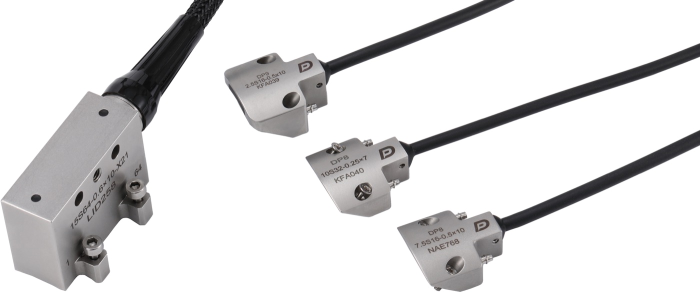
Laterally Focused Array Probe Series
Acoustic matching
Acoustically matched with Rexolite.
Focused beam
The array element is curved along its length and the beam is focused in the secondary axis. The focal spot of the sound field is therefore much smaller, the energy more concentrated and the ability to detect small flaws higher.
Use with scanners
DP8 and DP38 series probes, together with the Doppler Cobra scanner and a wedge, allow automated and semi-automated inspection of pipelines with an outer diameter from 20 mm to 115 mm.
Laterally focused array probes — specifications
| Model | Frequency (MHz) | Elements | Pitch (mm) | Active Aperture (mm) | Elevation (mm) | Physical focusing radius (mm) | Long (mm) | Width (mm) | Height (mm) | Case Type |
|---|---|---|---|---|---|---|---|---|---|---|
| 5S16-0.5×10 | 5 | 16 | 0.5 | 8 | 10 | R35 | 24.64 | 22 | 10 | DP8 |
| 7.5S16-0.5×10 | 7.5 | 16 | 0.5 | 8 | 10 | R35 | 24.64 | 22 | 10 | DP8 |
| 7.5S32-0.25×10 | 7.5 | 32 | 0.25 | 8 | 10 | R35 | 24.64 | 22 | 10 | DP8 |
| 10S32-0.25×10 | 10 | 32 | 0.25 | 8 | 10 | R35 | 24.64 | 22 | 10 | DP8 |
| 10S32-0.25×8 | 10 | 32 | 0.25 | 8 | 8 | R20 | 24.76 | 22 | 11 | DP38 |
| 2S16-0.5×10 | 2 | 16 | 0.5 | 8 | 10 | R80 | 25 | 22 | 14 | DP9 |
| 2.5S16-0.5×10 | 2.5 | 16 | 0.5 | 8 | 10 | R80 | 25 | 22 | 14 | DP9 |
| 5S32-0.6×10 | 5 | 32 | 0.6 | 19.2 | 10 | R80 | 23 | 28.5 | 23 | DP29 |
| 7.5S32-0.6×10 | 7.5 | 32 | 0.6 | 19.2 | 10 | R80 | 23 | 28.5 | 23 | DP29 |
| 5S64-0.6×10 | 5 | 64 | 0.6 | 38.4 | 10 | R35 | 42.5 | 28.5 | 24.5 | DP7 |
| 7.5S64-0.6×10 | 7.5 | 64 | 0.6 | 38.4 | 10 | R35 | 42.5 | 28.5 | 24.5 | DP7 |
| 10S64-0.6×10 | 10 | 64 | 0.6 | 38.4 | 10 | R35 | 42.5 | 28.5 | 24.5 | DP7 |
Near-wall Probe Series
The distance from the edge of the first and last element to the outside of the housing is 1 mm.
Acoustic matching
Acoustically matched with Rexolite.
Smaller blind spots
Smaller blind spots at both ends of the probe.
C-scan imaging
C-scan imaging combined with an encoder is very well suited to detecting delamination, disbonds and porosity in composites.
Near-wall Probes — specifications
| Model | Frequency (MHz) | Elements | Pitch (mm) | Active Aperture (mm) | Elevation (mm) | Long (mm) | Width (mm) | Height (mm) | Case Type |
|---|---|---|---|---|---|---|---|---|---|
| 7.5L32-0.5×7 | 7.5 | 32 | 0.5 | 16 | 7 | 18 | 18 | 20 | DP44 |
| 5L32-1.0×7 | 5 | 32 | 1.0 | 32 | 7 | 34 | 19 | 25 | DP55 |
| 5L64-1.0×7 | 5 | 64 | 1.0 | 64 | 7 | 66 | 19 | 20 | DP22 |
| 5L128-1.0×7 | 5 | 128 | 1.0 | 128 | 7 | 130 | 21 | 35 | DP33 |
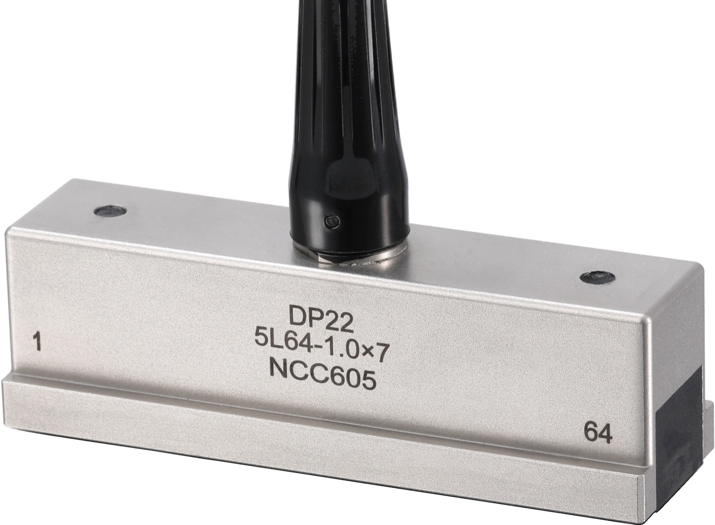
Water Immersion Probe Series (linear array)
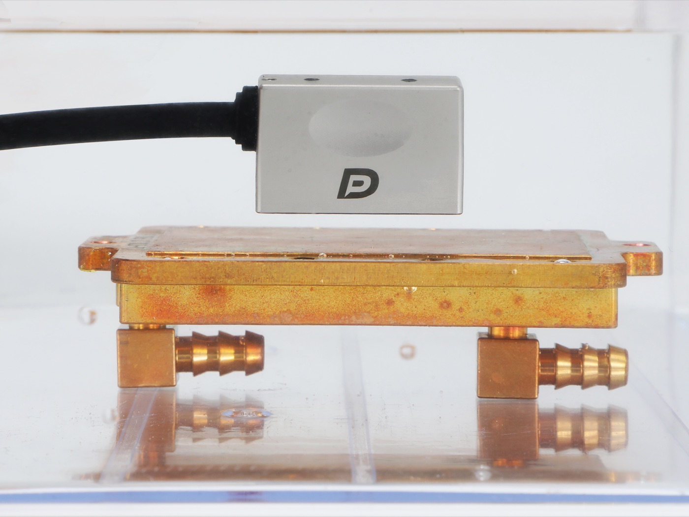
Water matching
Acoustic impedance matching water.
Case
The shell material is corrosion-resistant stainless steel.
Waterproofing
Waterproof performance within 1 m underwater.
In-line operation
Combined with an automation system, online detection can be carried out.
Water Immersion Probes — specifications
| Model | Frequency (MHz) | Elements | Pitch (mm) | Active Aperture (mm) | Elevation (mm) | Long (mm) | Width (mm) | Height (mm) | Case Type |
|---|---|---|---|---|---|---|---|---|---|
| 20L64-0.4×5 | 20 | 64 | 0.4 | 25.6 | 5 | 32 | 11 | 20 | DP19 |
| 5L64-1.0×7 | 5 | 64 | 1.0 | 64 | 7 | 75 | 19 | 30 | DP18 |
| 7.5L64-1.0×7 | 7.5 | 64 | 1.0 | 64 | 7 | 75 | 19 | 30 | DP18 |
| 5L128-0.8×10 | 5 | 128 | 0.8 | 102.4 | 10 | 114 | 22 | 30 | DP20 |
| 7.5L128-0.8×10 | 7.5 | 128 | 0.8 | 102.4 | 10 | 114 | 22 | 30 | DP20 |
Immersion Probe Series (self-focusing linear array)
Water matching
Acoustic impedance matching water.
Focused beam
The array element is curved along its length and the beam is focused in the secondary axis. The focal spot of the sound field is much smaller, the energy more concentrated and the ability to detect small flaws higher.
Case
The shell material is corrosion-resistant stainless steel.
Waterproofing
Waterproof performance within 1 m underwater.
In-line operation
Combined with an automation system, online detection can be carried out.
Immersion Probes — specifications
| Model | Frequency (MHz) | Elements | Pitch (mm) | Active Aperture (mm) | Elevation (mm) | Physical focusing radius (mm) | Long (mm) | Width (mm) | Height (mm) | Case Type |
|---|---|---|---|---|---|---|---|---|---|---|
| 18S64-0.2×5 | 18 | 64 | 0.2 | 12.8 | 5 | R35 | 22 | 12 | 26.48 | DP48 |
| 20S128-0.2×5 | 20 | 128 | 0.2 | 25.6 | 5 | R35 | 35 | 14 | 26.66 | DP49 |
| 15S64-0.6×10 | 15 | 64 | 0.6 | 38.4 | 10 | R35 | 43 | 16 | 26.87 | DP50 |
| 15S128-0.6×10 | 15 | 128 | 0.6 | 76.8 | 10 | R35 | 83 | 17 | 26.99 | DP51 |
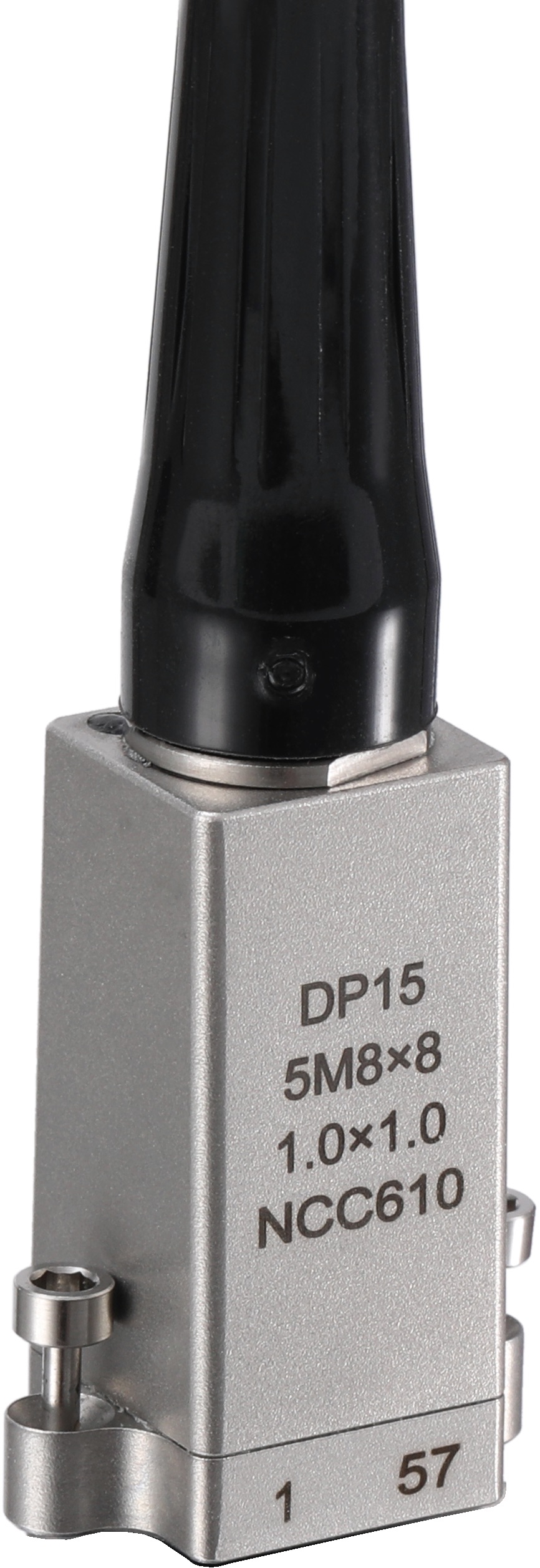
Matrix Array Probe Series
Acoustic matching
Acoustically matched with Rexolite.
3D imaging
Three-dimensional imaging capability.
Two-axis beam steering
The primary and secondary beams can both be steered, which gives a smaller spatial focal spot, more concentrated energy and a better signal-to-noise ratio.
Matrix Array Probes — specifications
| Model | Frequency (MHz) | Elements | Pitch Px (mm) | Pitch Py (mm) | Active Aperture Lx (mm) | Active Aperture Ly (mm) | Long (mm) | Width (mm) | Height (mm) | Case Type |
|---|---|---|---|---|---|---|---|---|---|---|
| 5M8×8-1.0×1.0 | 5 | 64 (Primary 8 / Secondary 8) | 1.0 | 1.0 | 8 | 8 | 21 | 13 | 28 | DP15 |
| 7.5M8×8-1.0×1.0 | 7.5 | 64 (Primary 8 / Secondary 8) | 1.0 | 1.0 | 8 | 8 | 21 | 13 | 28 | DP15 |
| 10M8×8-1.0×1.0 | 10 | 64 (Primary 8 / Secondary 8) | 1.0 | 1.0 | 8 | 8 | 21 | 13 | 28 | DP15 |
| 5M16×8-1.5×1.5 | 5 | 128 (Primary 16 / Secondary 8) | 1.5 | 1.5 | 24 | 12 | 30 | 28 | 35 | DP35 |
| 10M16×8-1.5×1.5 | 10 | 128 (Primary 16 / Secondary 8) | 1.5 | 1.5 | 24 | 12 | 30 | 28 | 35 | DP35 |
Integrated Wedge Probe Series
Permanent bond
The wafer and wedge are permanently fixed — no coupling agent is needed between them during testing.
Smaller size
The wedge is built in, so the overall probe size is smaller and convenient for detection in narrow spaces.
Angle beam inspection
Direct contact scanning with angle is possible.
Customised versions
A probe with an integrated wedge can be made to requirement, including a contact surface matched to a specific curved component.
Integrated Wedge Probes — specifications
| Model | Frequency (MHz) | Elements | Pitch (mm) | Active Aperture (mm) | Elevation (mm) | Refract angle | Long (mm) | Width (mm) | Height (mm) | Case Type |
|---|---|---|---|---|---|---|---|---|---|---|
| 5L12-0.5×6 | 5 | 12 | 0.5 | 6 | 6 | 55° SW (steel) | 24.87 | 13 | 10.35 | DP16 |
| 5L12-0.5×6 | 5 | 12 | 0.5 | 6 | 6 | 45° SW (aluminium) | 25 | 9 | 10.42 | DP36 |
| 5L12-0.5×6 | 5 | 12 | 0.5 | 6 | 6 | 45° LW (aluminium) | 28 | 9 | 12 | DP46 |
| 4L16-0.5×9 | 4 | 16 | 0.5 | 8 | 9 | 58° SW (steel) | 27 | 16.56 | 22 | DP45 |
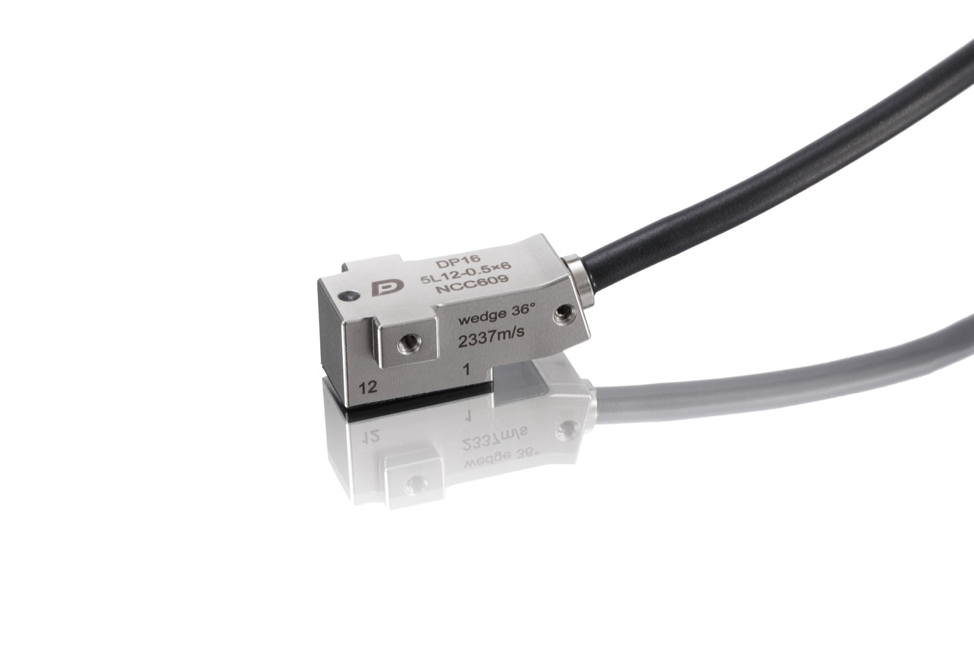
Water Bag Probe Series
Less clutter
The use of a water jacket wedge and its special design reduce the influence of interference compared with a conventional wedge.
Flexible coupling surface
The bottom of the water jacket wedge is a replaceable, flexible contact surface, which makes it possible to inspect components of irregular curvature without damaging their surface.
PE pipe electrofusion joints
Combined with a Doppler scanner and water jacket wedge it is used to inspect electrofusion butt joints of PE pipelines.
Water Bag Probes — specifications
| Model | Frequency (MHz) | Elements | Pitch (mm) | Active Aperture (mm) | Elevation (mm) | Long (mm) | Width (mm) | Height (mm) | Case Type |
|---|---|---|---|---|---|---|---|---|---|
| 4L64-0.8×10 | 4 | 64 | 0.8 | 51.2 | 10 | 66 | 35 | 25 | C45 |
| 2.5L64-1.0×7 | 2.5 | 64 | 1.0 | 64 | 7 | 79 | 35 | 35 | Z63 |
| 5L128-0.6×10 | 5 | 128 | 0.6 | 76.8 | 10 | 94 | 36 | 25 | WD94 |
| 4L128-0.8×10 | 4 | 128 | 0.8 | 102.4 | 10 | 120 | 36 | 25 | WD83 |
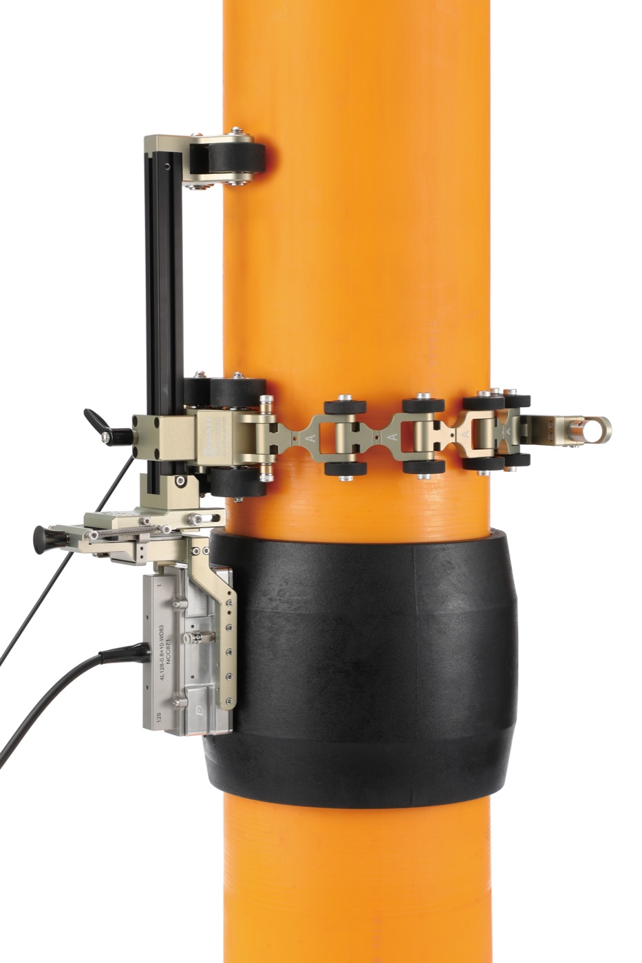
Soft Protective Film Probe Series
Replaceable protective film
At the front there is a replaceable soft protective membrane with a fixing sleeve — this extends probe life and gives reliable coupling on rough surfaces.
Ergonomics and scan coverage
Ergonomic housing, 0° longitudinal wave incidence, support for inspecting thick components (castings, forgings, solid shafts) with S-scan coverage from +30° to −30°.
Soft Protective Film Probes — specifications
| Model | Frequency (MHz) | Elements | Pitch (mm) | Active Aperture (mm) | Elevation (mm) | Diameter (mm) | Height (mm) | Case Type |
|---|---|---|---|---|---|---|---|---|
| 2L16-1.0×16 | 2 | 16 | 1.0 | 16 | 16 | Φ46 | 59 | DP25 |
| 4L16-1.0×16 | 4 | 16 | 1.0 | 16 | 16 | Φ46 | 59 | DP25 |
| 2.25L32-0.5×16 | 2.25 | 32 | 0.5 | 16 | 16 | Φ46 | 59 | DP25 |
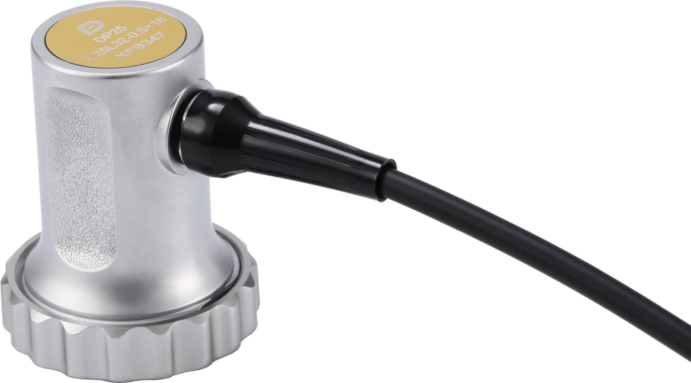
Wheel Probe Series
Coupling and encoder
Its own water storage coupling system and encoder give good coupling and allow efficient C-scan imaging.
Tyre material
Tyre material with extremely low attenuation is used.
Angle adjustment
An optional angle adjustment block allows the probe incidence angle to be set from 0° to 20°.
Automatic operation
Combined with an automated scanning device it is suitable for inspecting large flat surfaces or surfaces of slight curvature.
Wheel Probes — specifications
| Model | Frequency (MHz) | Elements | Pitch (mm) | Active Aperture (mm) | Elevation (mm) | Long (mm) | Width (mm) | Height (mm) | Case Type |
|---|---|---|---|---|---|---|---|---|---|
| 5L64-0.8×6.4 | 5 | 64 | 0.8 | 51.2 | 6.4 | 128 | 25 | 25 | E96 |
| 7.5L64-0.8×6.4 | 7.5 | 64 | 0.8 | 51.2 | 6.4 | 128 | 25 | 25 | E96 |
| 10L64-0.8×6.4 | 10 | 64 | 0.8 | 51.2 | 6.4 | 128 | 25 | 25 | E96 |
| 1L64-1.5×22 | 1 | 64 | 1.5 | 96 | 22 | 166 | 40 | 40 | G79 |
| 1L128-1.0×22 | 1 | 128 | 1.0 | 128 | 22 | 210 | 42 | 42 | MY88 |
| 2.25L128-1.0×22 | 2.25 | 128 | 1.0 | 128 | 22 | 210 | 42 | 42 | MY88 |
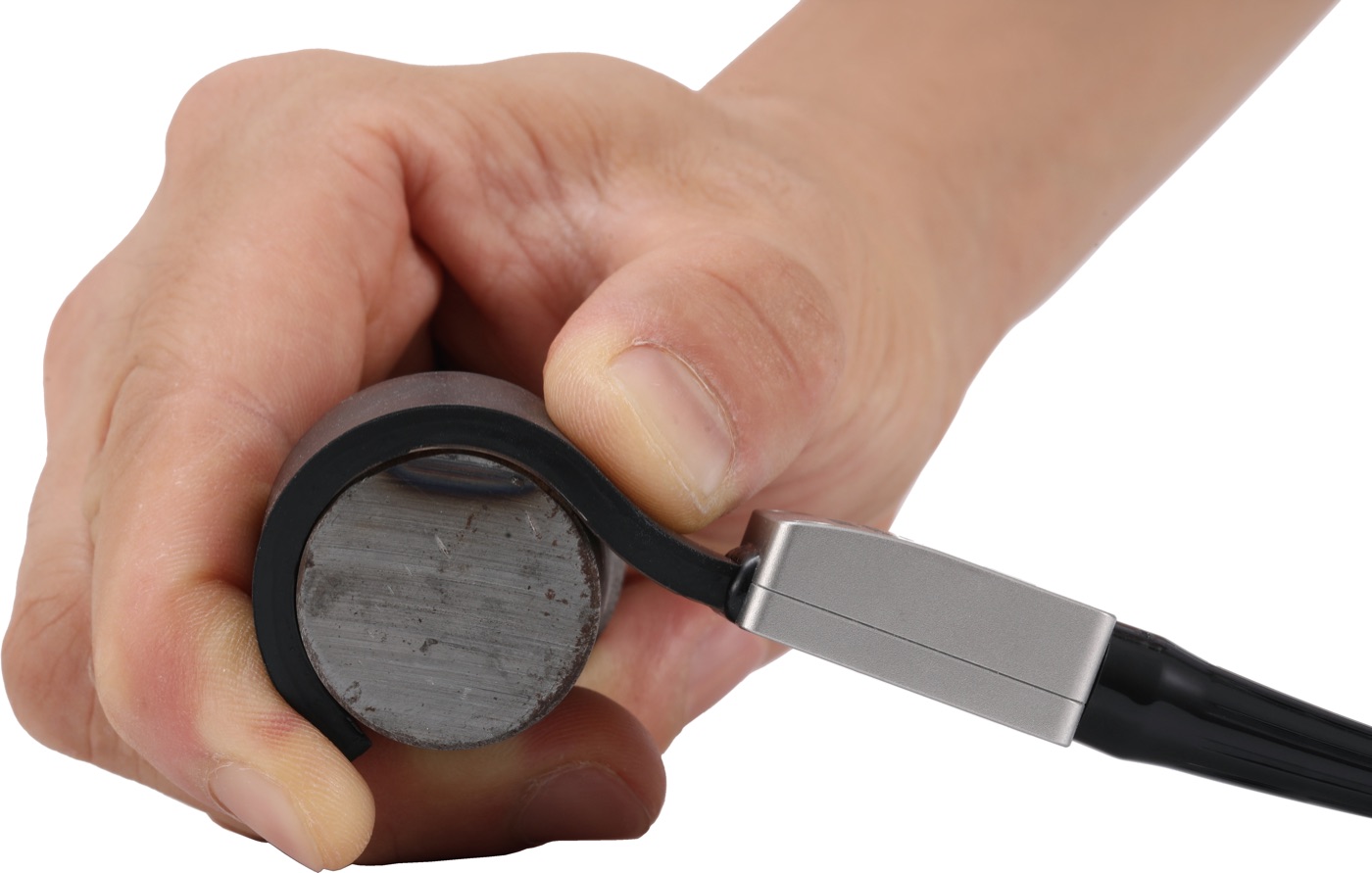
Flexible Probe Series
Variable curvature
The primary axis can bend to follow the shape of the component surface, with variable curvature and a minimum bending radius of 30 mm.
Access to narrow spaces
The minimum thickness of the flexible part is 3 mm, which allows detection in narrow spaces.
Use with scanner
Combined with a Doppler scanning device it is used for corrosion inspection and thickness measurement of pipes and bars of various sizes.
Flexible Probes — specifications
| Model | Frequency (MHz) | Elements | Pitch (mm) | Active Aperture (mm) | Elevation (mm) | Long (mm) | Width (mm) | Height (mm) | Case Type |
|---|---|---|---|---|---|---|---|---|---|
| 5S64-0.5×10 | 5 | 64 | 0.5 | 32 | 10 | 80 | 19 | 4 | DP26 |
| 7.5S64-0.5×10 | 7.5 | 64 | 0.5 | 32 | 10 | 80 | 19 | 4 | DP26 |
| 5S64-1.0×10 | 5 | 64 | 1.0 | 64 | 10 | 150 | 29 | 4 | DP27 |
| 7.5S64-1.0×10 | 7.5 | 64 | 1.0 | 64 | 10 | 150 | 29 | 4 | DP27 |
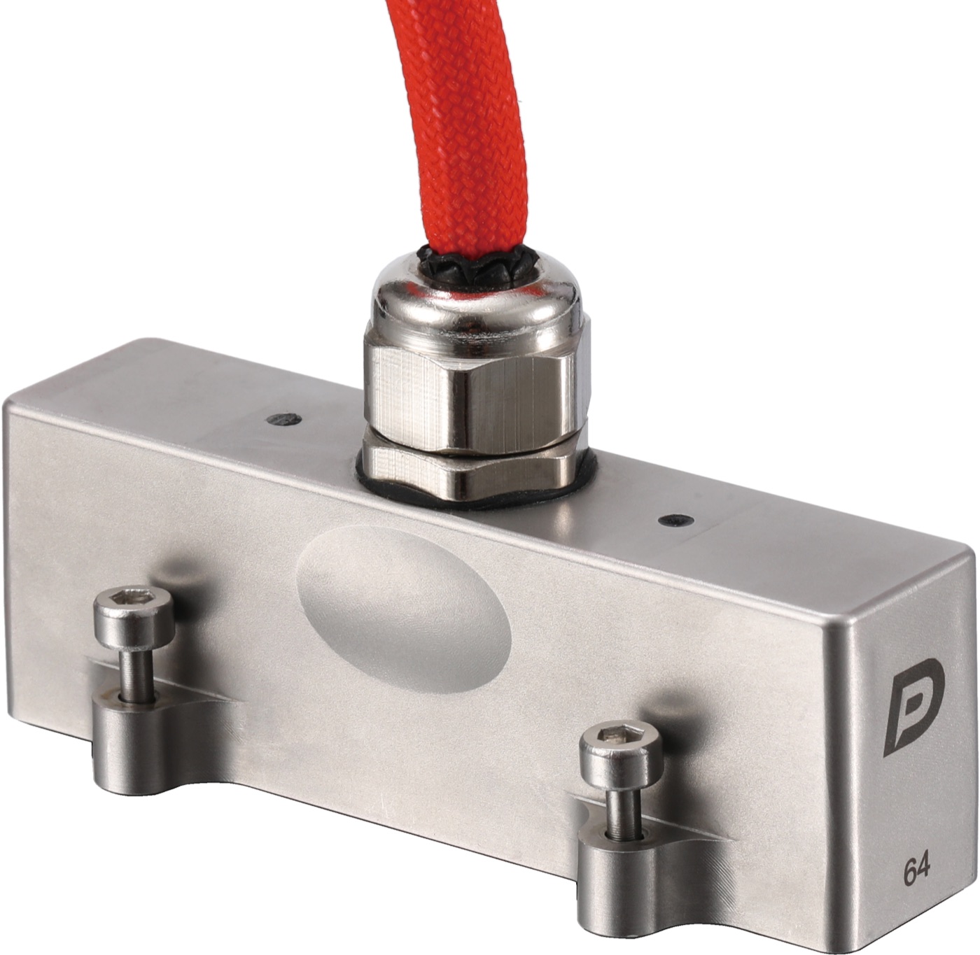
High Temperature Probe Series
Continuous inspection up to 150°C without cooling
The probe is heat resistant and, combined with a Doppler high temperature wedge, allows continuous inspection on a component with a surface temperature of 150°C, without cooling.
0° longitudinal wave or angled wedge
It can be used as a 0° longitudinal wave probe or with a high temperature wedge at an angle.
Second generation up to 350°C
The improved second-generation high temperature probe, combined with a Doppler high temperature wedge, works for extended periods at a component surface temperature of 350°C.
High Temperature Probes — specifications
| Model | Frequency (MHz) | Elements | Pitch (mm) | Active Aperture (mm) | Elevation (mm) | Long (mm) | Width (mm) | Height (mm) | Case Type | High-temperature type |
|---|---|---|---|---|---|---|---|---|---|---|
| 2.25L32-1.0×10 | 2.25 | 32 | 1.0 | 32 | 10 | 36 | 28.5 | 23 | DP28 | HT (150°C) |
| 5L32-1.0×10 | 5 | 32 | 1.0 | 32 | 10 | 36 | 28.5 | 23 | DP28 | HT (150°C) |
| 5L64-1.0×10 | 5 | 64 | 1.0 | 64 | 10 | 70 | 28.5 | 23 | DP5 | HT (150°C) |
| 5L32-0.6×10 | 5 | 32 | 0.6 | 19.2 | 10 | 28.5 | 23 | 23 | MD2 | HEHT (350°C) |
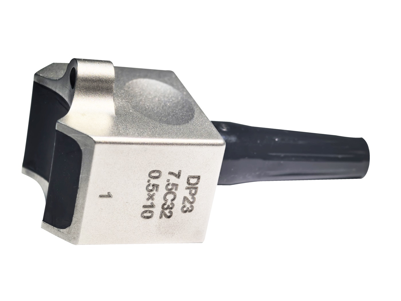
R-angle Probe Series
Acoustic matching
Acoustically matched with Rexolite.
Composite fillet inspection
Used to inspect the fillet of composite materials — a single scan covers the whole fillet area.
Normal incidence
The beams of all elements strike the rounded surface at 90°, and the incidence mode is close to inspection of a flat surface.
Inspection from both sides
With different wedges the fillet can be inspected from both the inside and the outside.
R-angle Probes — specifications
| Model | Frequency (MHz) | Elements | Pitch (mm) | Active Aperture (mm) | Elevation (mm) | Radius (mm) | Long (mm) | Width (mm) | Height (mm) | Case Type |
|---|---|---|---|---|---|---|---|---|---|---|
| 7.5C32-0.5×10 | 7.5 | 32 | 0.5 | 16 | 10 | 11 | 28 | 30 | 25 | DP23 |
| 5C32-1.47×10 | 5 | 32 | 1.47 | 47.04 | 10 | 30 | 70.18 | 30 | 35.52 | DP39 |
| 5C64-0.735×10 | 5 | 64 | 0.735 | 47.04 | 10 | 30 | 70.18 | 30 | 35.52 | DP39 |
| 10C64-0.735×10 | 10 | 64 | 0.735 | 47.04 | 10 | 30 | 70.18 | 30 | 35.52 | DP39 |
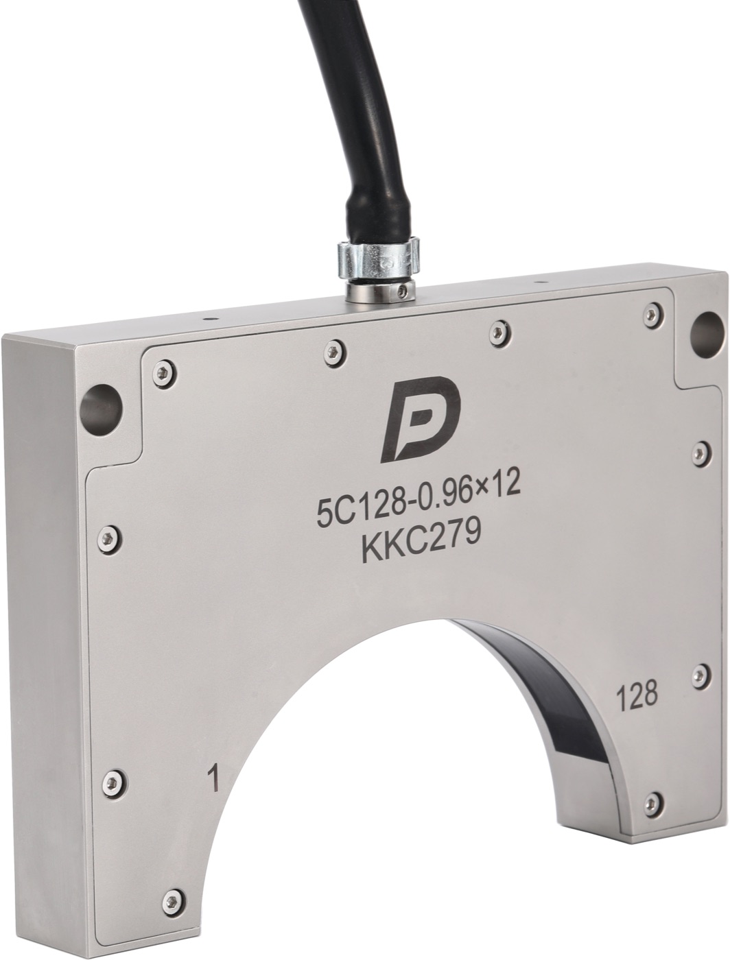
Concave Array Probe Series
Water matching
Acoustic impedance matching water.
Case
The shell material is corrosion-resistant stainless steel.
Waterproofing
Waterproof performance within 1 m underwater.
In-line operation
Combined with an automation system, online detection can be carried out.
Use with scanner
With a Doppler scanning device it allows automated or semi-automated corrosion inspection and thickness measurement of pipes and bars of various sizes.
Concave Array Probes — specifications
| Model | Frequency (MHz) | Elements | Pitch (mm) | Active Aperture (mm) | Elevation (mm) | Radius (mm) | Long (mm) | Width (mm) | Height (mm) | Case Type |
|---|---|---|---|---|---|---|---|---|---|---|
| 10C128-0.6×9 | 10 | 128 | 0.6 | 76.8 | 9 | 40 | 94 | 20 | 60 | DP43 |
| 5C128-0.95×12 | 5 | 128 | 0.95 | 121.6 | 12 | 50 | 120 | 23 | 70 | DP24 |
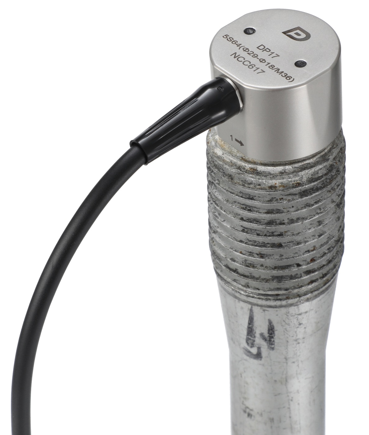
Bolt Probe Series
In-service inspection without disassembly
In-service inspection can be carried out on bolts in working state without disassembly, which greatly shortens maintenance time.
Single coupling
High detection accuracy and efficiency — the whole bolt is inspected with a single coupling.
Applications
Detection of bolt defects in bridges, high-speed rail and wind power.
Range
Suitable for M20–M100 bolt inspection.
Bolt Probes — specifications
| Model | Frequency (MHz) | Elements | Pitch (mm) | Inner Diameter (mm) | Outer Diameter (mm) | Bolt Diameter (mm) | Diameter (mm) | Height (mm) | Case Type |
|---|---|---|---|---|---|---|---|---|---|
| 5S64(Φ15-Φ8) | 5 | 64 | 0.56 | 8 | 15 | M20 | 22 | 25 | DP37 |
| 5S64(Φ29-Φ18) | 5 | 64 | 1.15 | 18 | 29 | M36 | 35 | 25 | DP17 |
| 5S64(Φ42-Φ30) | 5 | 64 | 1.77 | 30 | 42 | M48 | 47 | 25 | DP47 |
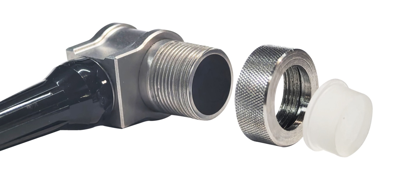
Spot Welding Probe Series
Acoustic matching
Acoustically matched with Rexolite.
Transmit-receive mode
The probe works in self-transmit and self-receive mode, so it gives information about both the surface and the interior of the component and an image of the weld nugget across its whole area.
Replaceable delay block
At the front there is a replaceable delay block with a fixing sleeve — this extends probe life and eliminates the near-field dead zone.
Application
For resistance spot welding and other welding spot detection.
Multi-element probe
An 8 × 8 array, that is 64 elements — the image covers the whole weld nugget in a single placement.
Spot Welding Probes — specifications
| Model | Frequency (MHz) | Elements | Pitch Px (mm) | Pitch Py (mm) | Active Aperture Lx (mm) | Active Aperture Ly (mm) | Long (mm) | Width (mm) | Height (mm) | Case Type |
|---|---|---|---|---|---|---|---|---|---|---|
| 15M8×8-1.0×1.0 | 15 | 64 (Primary 8 / Secondary 8) | 1.0 | 1.0 | 8 | 8 | 24 | 20 | 30 | DP41 |
| 15M8×8-1.5×1.5 | 15 | 64 (Primary 8 / Secondary 8) | 1.5 | 1.5 | 12 | 12 | 26.5 | 25 | 30 | DP42 |
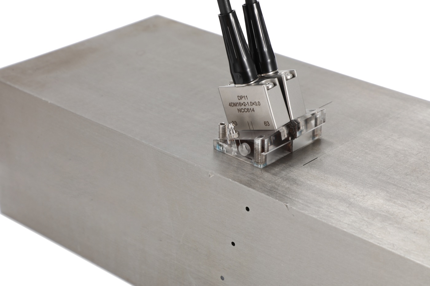
Dual-Linear Array / Dual Matrix Probe Series
Acoustic matching
Acoustically matched with Rexolite.
Minimal blind zone
The probe works in transmit-receive mode and has a very small dead zone at the surface, which significantly improves near-surface resolution on the component under test.
Advantage over conventional dual-crystal probes
Compared with a conventional dual-element probe, this series offers wider coverage, better imaging and a more favourable signal-to-noise ratio.
Application
For welding seam detection of austenitic and dissimilar materials.
Dual-Linear Array / Dual Matrix Probes — specifications
| Model | Frequency (MHz) | Elements | Pitch Px (mm) | Pitch Py (mm) | Active Aperture Lx (mm) | Active Aperture Ly (mm) | Long (mm) | Width (mm) | Height (mm) | Case Type |
|---|---|---|---|---|---|---|---|---|---|---|
| 5DL16-0.75×5 | 5 | 32 (Dual linear array) / 64 (Dual linear array) | 0.75 | / | 12 | 5 | 24 | 23.6 | 19.72 | DP12 |
| 10DL32-0.375×5 | 10 | 32 (Dual linear array) / 64 (Dual linear array) | 0.375 | / | 12 | 5 | 24 | 23.6 | 19.72 | DP12 |
| 2.25DL32-0.6×12 | 2.25 | 32 (Linear array) / 64 (Dual linear array) | 0.6 | / | 19.2 | 12 | 33.8 | 17 | 25 | DP13 |
| 4DL32-1.0×10 | 4 | 32 (Linear array) / 64 (Dual linear array) | 1.0 | / | 32 | 10 | 46 | 16 | 20 | DP14 |
| 2.25DL64-1.0×12 | 2.25 | 64 (Linear array) / 128 (Dual linear array) | 1.0 | / | 64 | 12 | 80.2 | 16.5 | 25 | DP34 |
| 2.25DM7×4-2.71×3.0 | 2.25 | 28 (Matrix array) / 56 (Dual matrix array) | 2.71 | 3.0 | 18.97 | 12 | 33.8 | 16 | 20 | DP10 |
| 4DM16×2-1.0×3.0 | 4 | 32 (Matrix array) / 64 (Dual matrix array) | 1.0 | 3.0 | 16 | 6 | 28.5 | 10 | 20 | DP11 |
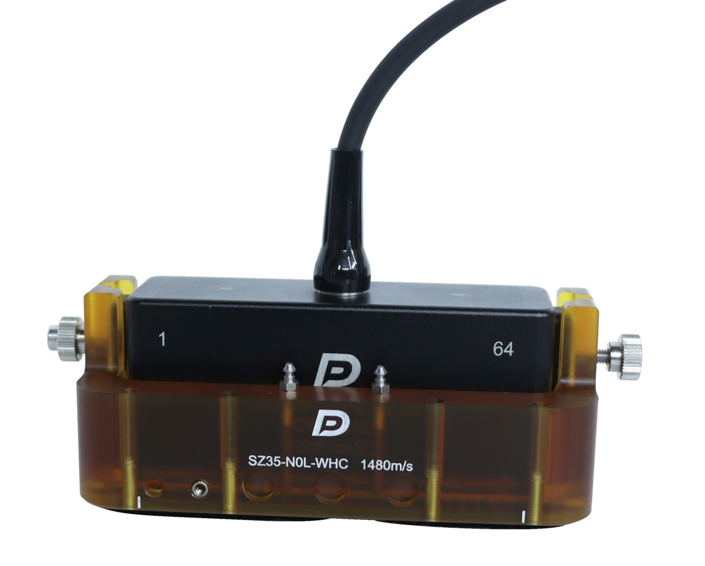
Wind Power Probe Series
Water matching
Acoustic impedance matching water.
Water wedge
The special water wedge can be used to detect the adhesion of wind turbine blades.
High-attenuation materials
Suitable for detecting workpieces with high attenuation and thick materials.
Wind Power Probes — specifications
| Model | Frequency (MHz) | Elements | Pitch (mm) | Active Aperture (mm) | Elevation (mm) | Long (mm) | Width (mm) | Height (mm) | Case Type |
|---|---|---|---|---|---|---|---|---|---|
| 0.5L64-1.5×22 | 0.5 | 64 | 1.5 | 96 | 22 | 120 | 34 | 50 | Z35 |
| 1L64-1.5×22 | 1 | 64 | 1.5 | 96 | 22 | 120 | 34 | 50 | Z35 |
Other Special Probes
In line with the needs of inspection carried out on site, the manufacturer develops special probes to order. Some of the designs already built are listed below — Doppler is a good choice for difficult inspection scenarios.
Versions available to order
Multi-circle sector probe · self-focusing concave array probe · conical annular probe · multi-joint probe · through-type annular self-focusing convex array probe · through-type annular convex array probe · through-type annular convex matrix array probe · integrated self-focusing concave probe · circular array probe · annular hollow focusing probe.
Selection of Industrial Array Probes
A protective film with high acoustic transmittance can be applied directly to the surface of a phased array probe. As a result no 0° wedge is needed for the inspection, interference from multiple echoes on the bottom surface of the wedge is effectively eliminated, and the cost of inspection genuinely falls.
Cable sleeves
The corrugated sheath protects the cable against corrosion and external impact. The nylon braid increases protection while keeping the cable flexible. A metal corrugated tube further strengthens shielding and interference immunity, protecting the conductors against corrosion and impact.
Instructions for phased array probes
A blue protective film is applied to the probe surface to prevent scratching in transport — it must be removed before use, otherwise it will affect probe performance. The connector must never be forced in or out, so that the contacts are not damaged. The probe must be protected against impact. When not in use the probe should be stored closed, for example in its original case, so that it is not exposed to ambient conditions. The application of each probe type follows the relevant inspection standards — the manufacturer welcomes enquiries about solutions for non-standard scenarios.
Warranty description
The warranty period for Doppler phased array probes is normally one year. The warranty does not cover damage or wear resulting from improper use or accident, including: incorrect mounting; incorrect operation, such as striking the probe face or dismantling the probe; operation outside the permissible range, where the storage temperature is normally −30°C to 50°C and the operating temperature −20°C to 50°C; excessive excitation voltage, where the maximum repetition frequency is normally 10 kHz and continuous operation does not exceed 5 kHz at 100 V (details according to the probe test report); use of a couplant that does not meet the requirements.
General index of phased array probes
Doppler applies strict quality standards; the general product indicators follow the JB/T 11731-2013 test standard.
| Parameter | Value |
|---|---|
| Sensitivity conformity | ±2 dB |
| Sensitivity difference between batches | ±2 dB |
| Operating temperature | −20°C to 50°C |
| Storage temperature | −30°C to 50°C |
Wedges for array probes
Angle range
Wedges are normally used for shear wave (SW) or longitudinal wave (LW) inspection at angles from 30° to 70°, providing refraction angles of 0°, 45°, 55° and 60° in standard steel.
Anti-wear screws
Composite anti-wear screws can be used on easily scratched surfaces.
High-temperature version
The high temperature wedge is used in high temperature environments and withstands 260°C.
Customised versions
Wedge shape and parameters can be customised according to customer requirements.
Available types
Anti wear wedge · water wedge · angle wedge · dual array wedge · 0° wedge · high temperature wedge.
Wedge types
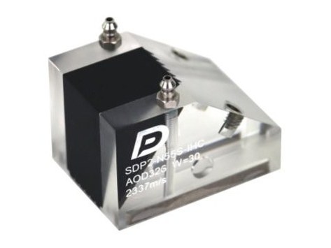
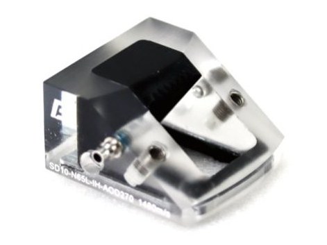
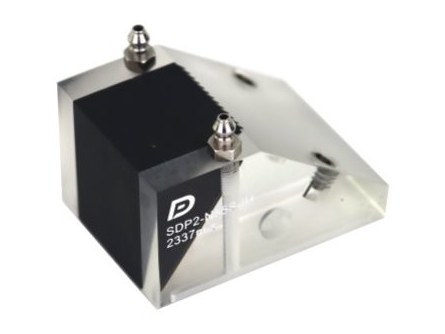
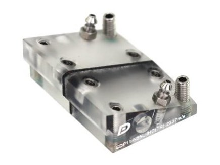
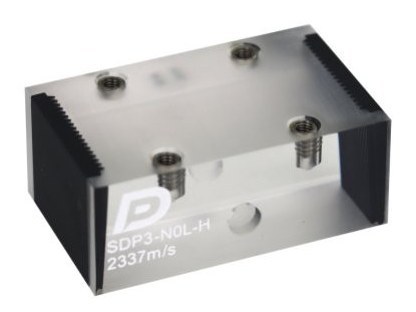
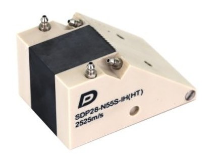
Wedges — specifications
| Wedge Type | Wedge Mode | Probe Type | Refract angle | Long (L) (mm) | Width (W) (mm) | Height (H) (mm) | Wedge Angle |
|---|---|---|---|---|---|---|---|
| 0° Wedge | SDP3-N0L-H | DP3 | 0° LW | 48 | 30 | 20 | 0° |
| Angle Wedge | SDP2-N55S-IH | DP2 | 55° SW | 41 | 30 | 26.64 | 36° |
| Anti Wear Wedge | SDP2-N55S-IHC-AOD326 | DP2 | 55° SW | 41 | 30 | 27.29 | Φ326 mm |
| Dual Array Wedge | SDP11-N55L-IHC (TR, roof angle 3.7°, F = 15) | DP11 | 55° LW | 30 | 40 | 14.96 | 18.7° |
| High Temperature Wedge | SDP28-N55S-IH(HT) | DP28 | 55° SW | 64 | 44 | 34 | 39.5° |
| Water wedge | SDP8-N65L-IH-AOD270 | DP8 | 65° LW | 23.96 | 22 | 13.12 | Φ270 mm |
Connectors and Adapters
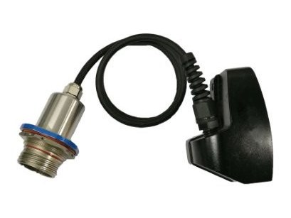
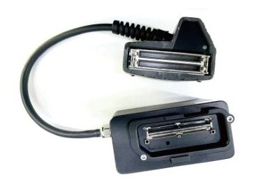
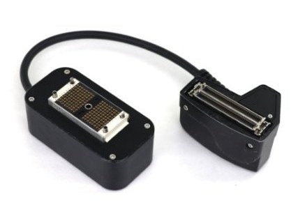
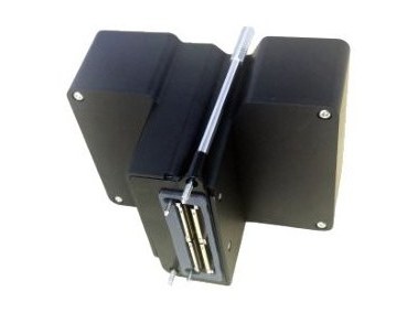
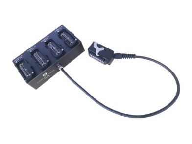
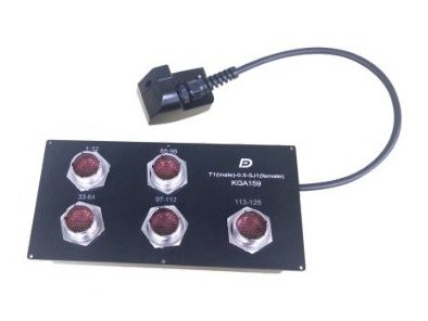
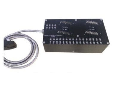
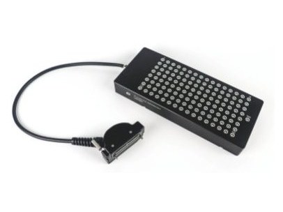
Doppler supplies connectors compatible with all the popular phased array probe types on the market — T1, P1, J1, H1, P1 (Quick lock), D2, D3, M1 and others.
Available connectors
T1: QLC-260P · P1: I-PEX 30056 · J1: D38999/26FF35SN · P1 (Quick lock) · D2: DL-260P · H1: Hypertronic.
Adapter box
The Doppler phased array probe connector adapter box allows free switching between the T1, P1, J1, H1, D1, D2, D3, M1 and other interfaces. It can be made to customer requirements.
Available adapters
T1 (plug) – J1 (socket), i.e. J1 on the probe side and T1 on the instrument side · T1 (plug) – P1 (socket) · T1 (plug) – H1 (socket) · P1 (plug) – T1 (socket), integrated adapter box · P1 (Quick lock, plug) – 4 × P1 (socket) · T1 (plug) – 5 × J1 (socket) · T1 (plug) – 4 × P1 / 40 × Lemo (socket) · P1 (plug) – 128 × Lemo (socket).
Connectors
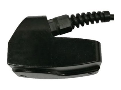
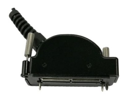
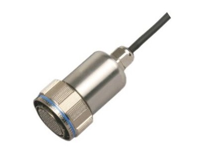
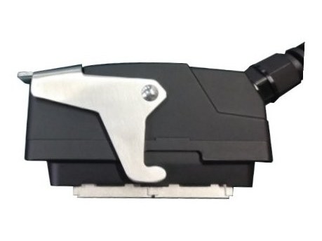
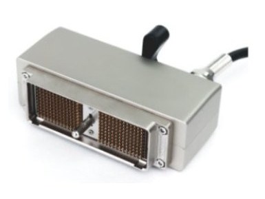
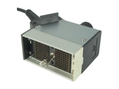
Adapters
MOS08 — Modular Axial Stepping Scanner
The MOS08 is a pipeline weld scanner with quick-release chain links. The innovative links make it easy and quick to move between different pipe diameters. A unique stepping axis allows accurate positioning during inspection: in corrosion mapping it gives continuous and even scanning, and in weld inspection on a curve it compensates for the change in distance by correcting the probe position.
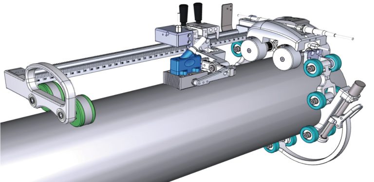
Quick-release links — instant change of pipe diameter
Stepping axis for precise probe positioning
Compensation for distance change on bend welds
MOS08 — Modular Axial Stepping Scanner — specifications
| Parameter | Value |
|---|---|
| Minimum pipe diameter | 100 mm |
| Stepping axis range | 250 mm (customisable) |
DSC06 — Plate/Pipe Corrosion & Base Material Scanner
The DSC06 was designed specifically for corrosion inspection of pipes and flat components. It uses local water immersion with a water layer of about 10 mm and a standard 64-element phased array probe. The design is compact and easy to carry and operate, which makes work on site considerably easier.
Local water immersion — stable acoustic coupling
64-element phased array probe as standard
Other water layers and element counts available to order
Compact, portable design
DSC06 — Plate/Pipe Corrosion & Base Material Scanner — specifications
| Parameter | Value |
|---|---|
| Standard range | pipes and planes from 127 mm |
| Minimum pipe diameter | 60 mm |
| Standard water layer | 14 mm |
FS01 — Corrosion Scanner for Wind Turbine Blades
The FS01 is a system intended primarily for manual inspection of wind turbine blades. Before use, make sure the probe is correctly connected to the encoder and that the surface of the component has no pronounced protrusions — this is a condition for the best inspection result.
Manual inspection of wind turbine blades
Probe working with encoder
FS06 — Elbow Corrosion Scanner
The FS06 is a scanner for corrosion inspection of bent and straight pipes. It consists of a flexible probe usable on various diameters, a guide wheel for smooth travel along the pipeline, a water jacket made to the pipe diameter and an encoder providing accurate position information. The operator controls the inspection with buttons on the scanner — they can move to the next line and start the inspection without leaving the component.
One flexible probe for many diameters
Guide wheel ensuring smooth travel
Buttons on the scanner — line feed and start inspection
C-scan imaging
FS06 — Elbow Corrosion Scanner — specifications
| Parameter | Value |
|---|---|
| Minimum elbow diameter | 102 mm |
| IP level | IP67 |
FS04 — Axial Straight Pipe Flexible Probe Scanner
The FS04 was designed for axial corrosion inspection of straight pipes. It consists of a magnetic wheel, a support frame, a water jacket, an encoder and a flexible probe. For pipes of different diameters the device requires a matching water jacket, made to order. When inspecting several parallel pipelines, check that the pipe centre spacing will not cause a collision.
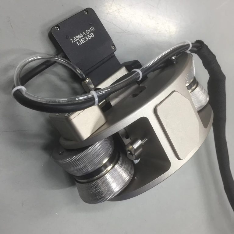
Magnetic wheel — stable adsorption and coupling
Water jacket made to the pipe diameter
Encoder recording the scan path
Changing diameter needs no probe change — only the water jacket
FS04 — Axial Straight Pipe Flexible Probe Scanner — specifications
| Parameter | Value |
|---|---|
| Diameter range | from 38 mm upwards |
| Water jacket tolerance | OD ±3 mm |
FS05 — Axial Straight Pipe Concave Array Probe Scanner
The FS05 is used for axial corrosion inspection of straight pipes. It consists of a magnetic wheel, a support frame, a water jacket, an encoder and a concave array probe. The water jacket and probe are selected according to the pipe diameter and the required water layer.
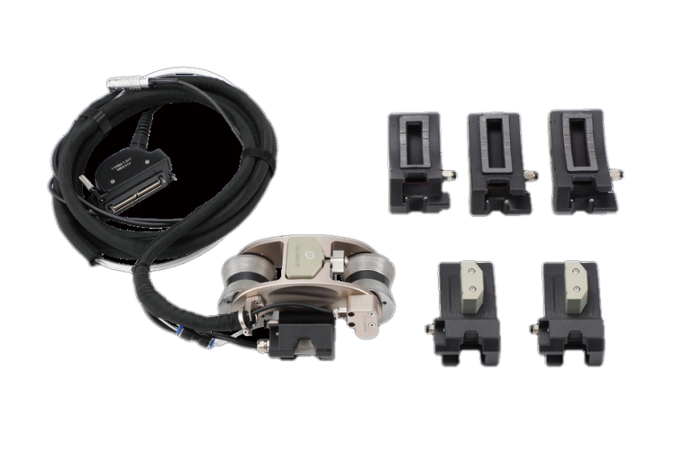
Concave array probe matched to the pipe curvature
Magnetic wheel — stable coupling
Water jacket and probe selected to the diameter
FS05 — Axial Straight Pipe Concave Array Probe Scanner — specifications
| Parameter | Value |
|---|---|
| Minimum customisable diameter | 19 mm |
| Typical range | OD 40–150 mm |
LS03 — 64-element Tyre Scanner
The LS03 is a multi-function tyre scanner designed for demanding inspection tasks. It combines fast phased array technology with a modular build. It is an easy-to-deploy alternative to a full two-dimensional encoding arrangement, and an effective substitute for immersion testing where conventional immersion technique cannot be applied.
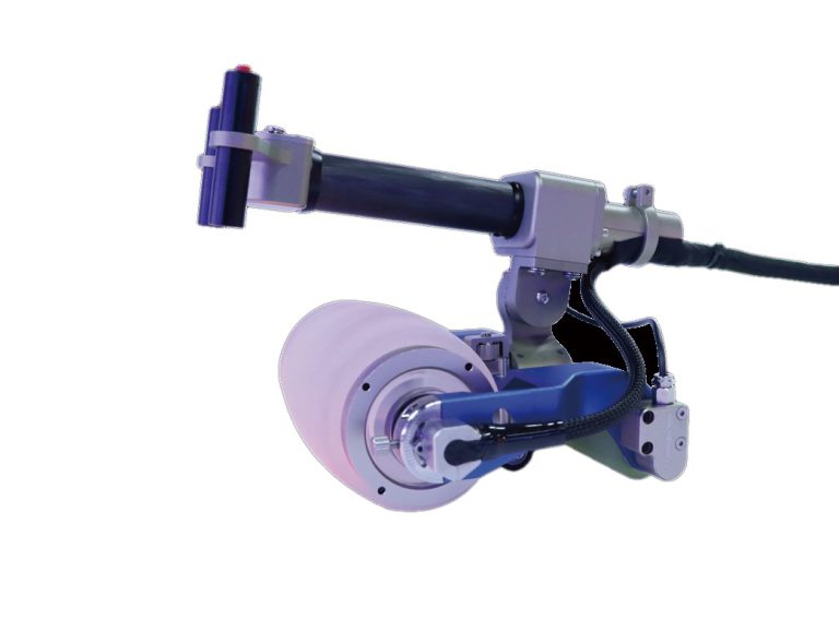
Modular design — probes of different frequencies can be exchanged
An alternative to immersion testing
Tyre material with special acoustic characteristics
LS03 — 64-element Tyre Scanner — specifications
| Parameter | Value |
|---|---|
| Probe | 64-element phased array |
LS06 — 128-element Tyre Scanner
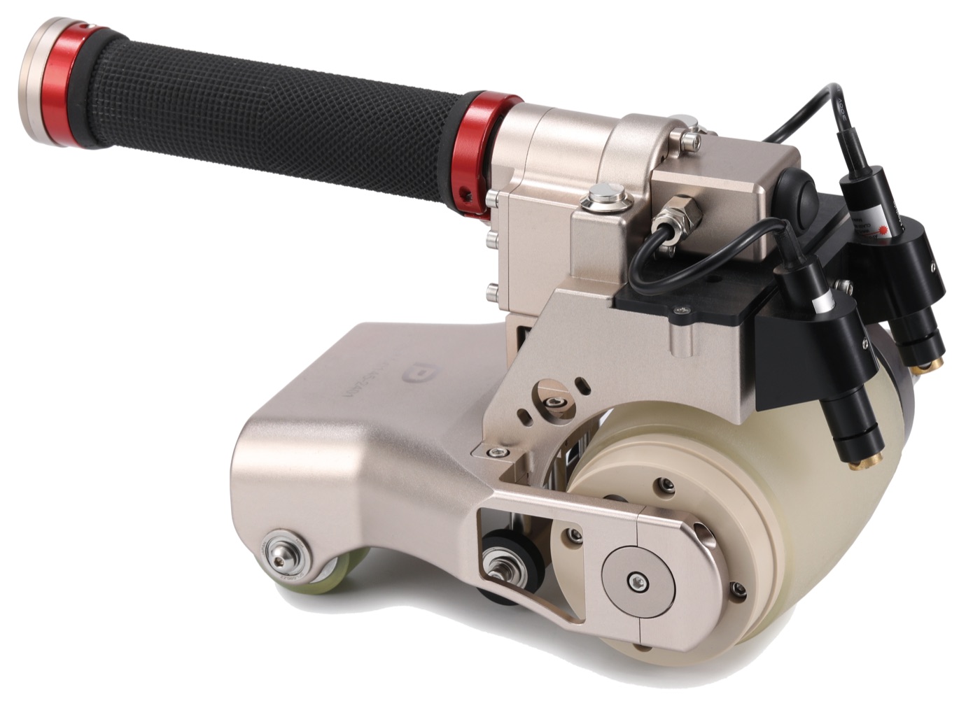
Compared with the LS03 scanner, the 128-element version brings a clear advance in design and performance. The housing is simpler in form and the handle is made of a composite that improves working comfort. Above all, however, the coverage is wider than on the LS03, which genuinely increases inspection throughput.
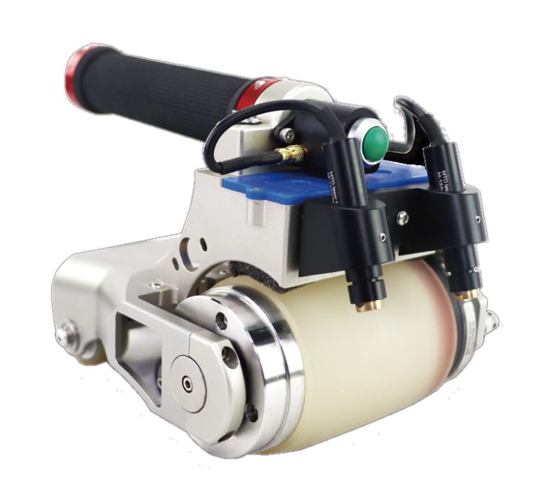
Portable two-dimensional scanning tool
Laser guidance — fast and accurate partition scanning
Configurable buttons: line feed, reset, rescan the current line
Composite grip
LS06 — 128-element Tyre Scanner — specifications
| Parameter | Value |
|---|---|
| Water layer inside the tyre | 25 mm |
| Probe | 128-element phased array |
LS13 / LS20 — Wind Turbine Blade Tyre Scanner
Wind turbine blade materials are difficult for non-destructive testing because they strongly attenuate ultrasound. This scanner combines efficient inspection with a design matched to glass-composite surfaces, which translates into accurate and repeatable results — and safe operation of wind farms.
Design matched to glass-composite surfaces, which strongly attenuate ultrasound
Developed for the material layouts typical of turbine blades — accurate, repeatable inspection
Straightforward alternative to full two-axis encoder setups
Replaces immersion testing where conventional immersion cannot be applied
LS13 / LS20 — Wind Turbine Blade Tyre Scanner — specifications
| Parameter | Value |
|---|---|
| LS13 (1L64) — water layer | 32 mm |
| LS13 (1L64) — thickness range | up to 60 mm |
| LS20 (1L128) — water layer | 42 mm |
| LS20 (1L128) — thickness range | up to 64 mm |
DSC03 — Heavy-duty Crawler
The DSC03 is a multi-function electric scanner intended to carry the weld scanning arm and the transverse corrosion scanning arm. It stands out for very high stability and a high payload. Adhesion is provided by a permanent magnet, so the device stays on the surface even if power is lost.
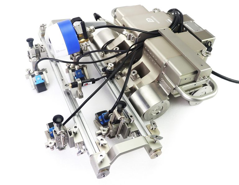
Permanent magnet — adsorption maintained after power failure
Scanning modes: horizontal, vertical, raster and sawtooth
Supports conventional UT, phased array and TOFD probes
1 to 4 probes as required
Vertical, horizontal and inverted movement
WiFi camera
Electric water pump for couplant supply (lift up to 20 m)
With the FC05 arm — longitudinal and circumferential weld inspection
DSC03 — Heavy-duty Crawler — specifications
| Parameter | Value |
|---|---|
| Crawler speed range | 5–120 mm/s |
| Scanning axis speed range | 10–100 mm/s |
| Power Supply | AC 220 V or DC 24 V |
| Operating temperature | −10°C to 50°C |
| IP level | IP66 |
| Circumferential scanning, inner wall | ID ≥ 2500 mm |
| Circumferential scanning, outer wall | OD ≥ 300 mm |
| Axial scanning, outer wall | OD ≥ 500 mm |
| Scanning arm stroke (DSC03+) | 300 mm |
DSC05 — Small Pipeline Longitudinal Travel Scanner
The DSC05 is an advanced, remotely controlled inspection crawler designed for magnetic surfaces, adhering firmly to materials such as carbon steel. It travels along the axis of the component and carries out the inspection using the mounted sensors. The design combines a drive body, an encoder module for accurate positioning, a magnetic wheel module, a probe holder module, a power module, a camera module and a remote control module. The operator can inspect places that are hard to reach or hazardous.
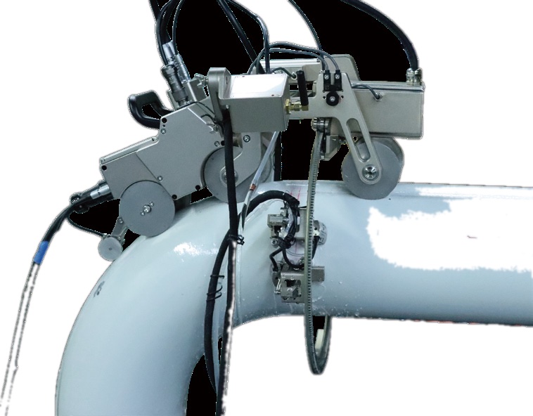
Remote control — inspection in hard-to-reach places
Magnetic wheels — stable adsorption on carbon steel
Camera module for visual observation
Modular design — quick change of inspection equipment
With the double-sided elbow scanner — straight pipe and elbow weld inspection
With the straight pipe corrosion scanner — two probes working simultaneously
Holder for two phased array probes
Customised holder also for non-magnetic materials
DSC05 — Small Pipeline Longitudinal Travel Scanner — specifications
| Parameter | Value |
|---|---|
| Pipe diameter range | 60–190 mm |
DSC39 — Straight Inner Pipe Auto-scanner
The DSC39 is an electric scanner designed for inspecting straight pipes and able to carry different probe types — phased array or eddy current. The standard configuration is suited to pipes with an inner diameter from 150 to 200 mm. For other sizes the manufacturer builds versions to order, matched to the specific diameter.
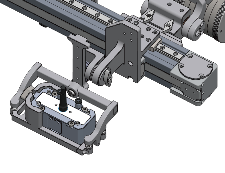
Supports phased array and eddy current probes
Customised versions for other diameters
DSC39 — Straight Inner Pipe Auto-scanner — specifications
| Parameter | Value |
|---|---|
| Standard range | ID 150–200 mm |
DSC40 — Weld/Corrosion Auto-scanner
The DSC40 is a multi-function electric scanner that meets different inspection requirements by changing the arm: for weld scanning, for transverse corrosion scanning or for scanning along a curve. It stands out for its light construction, high payload and simple operation.
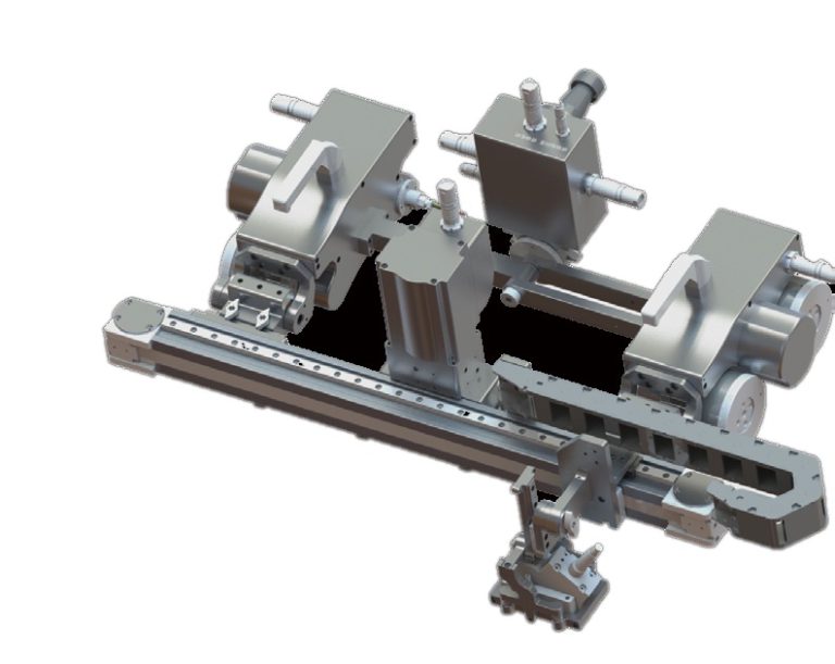
Permanent magnet — adsorption maintained after power failure
Interchangeable arms: welds, transverse corrosion, arc scanning
Supports conventional UT, phased array and TOFD probes
1 to 4 probes for weld inspection
Scanning modes: horizontal, vertical, raster and sawtooth
With the FC05 arm — longitudinal and circumferential welds (up to 6 probes on longitudinal seams)
DSC40 — Weld/Corrosion Auto-scanner — specifications
| Parameter | Value |
|---|---|
| Maximum load on a vertical plane | 12 kg |
| Crawler speed range | 5–150 mm/s |
| Scanning axis speed range | 10–100 mm/s |
| Power Supply | AC 220 V or DC 24 V |
| Operating temperature | −10°C to 50°C |
| IP level | IP66 |
| Circumferential scanning, inner wall | ID ≥ 460 mm |
| Circumferential scanning, outer wall | OD ≥ 200 mm |
| Axial scanning, outer wall | OD ≥ 400 mm |
| Max. probe width | 50 mm |
MOS01 — Mouse-type Girth Weld Scanner
The MOS01 is a multi-purpose scanner designed for industrial inspection, combining portability with high performance. It is fitted with an advanced encoder that guarantees the accuracy of the data collected. The mounting frame makes it easy to change probe types for a specific inspection task.
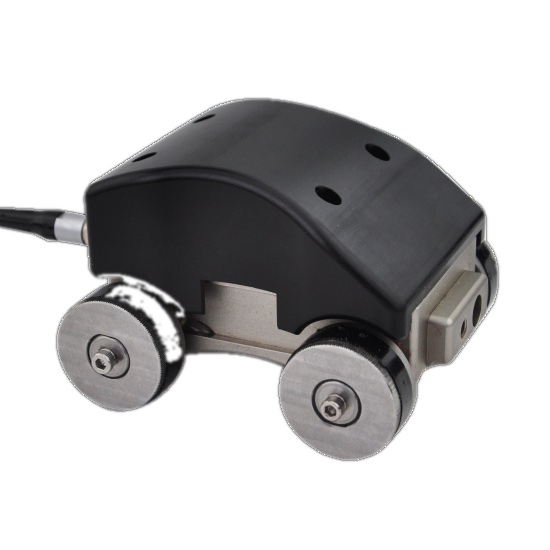
Mouse-type ergonomics — convenient and fast operation
Encoder concealed in the body — prevents slipping and data loss, extends service life
Four strong magnetic wheels with torsion spring — firm probe contact with the surface
Probe clamping direction adjustable by 90° — lateral and vertical scanning
Accessories for oblique parallel scanning
MOS01 — Mouse-type Girth Weld Scanner — specifications
| Parameter | Value |
|---|---|
| Diameter range | pipes above 100 mm |
MOS02 — Fillet Weld Scanner
The MOS02 inherits the portability, flexibility and wide applicability of the MOS01, and the added fillet weld guide considerably improves the accuracy and efficiency of fillet weld inspection. The guide eliminates probe drift during the inspection.
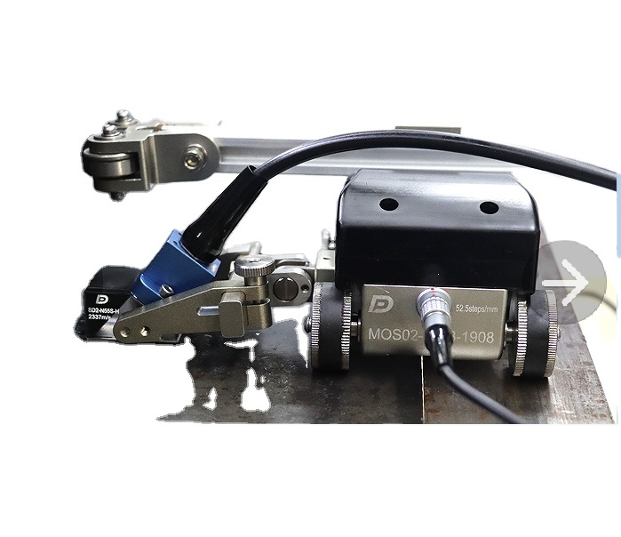
Fillet weld guide — no probe drift
Universality retained: general weld and corrosion inspection
High IP67 protection — work in wet and underwater environments
Mounting frame up to 49 mm, above 50 mm to order
MOS02 — Fillet Weld Scanner — specifications
| Parameter | Value |
|---|---|
| IP level | IP67 |
| Max. clamping frame width | 49 mm |
MOS20 — Narrow-contact Surface Scanner
The MOS20 is a compact weld scanner designed for demanding inspection conditions. It combines magnetic adhesion technology, stable mounting and an ergonomic grip. It performs particularly well in complex and confined working conditions.
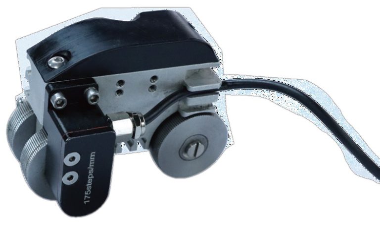
Magnetic adhesion
Narrow contact surface — inspection in tight spots
Ergonomic grip
MOS20 — Narrow-contact Surface Scanner — specifications
| Parameter | Value |
|---|---|
| Minimum pipe diameter | 114 mm |
MOS43 — Weld Scanner for limited probe travel
The scanner uses a magnetic design, so it adheres firmly to magnetic materials without additional fixing elements. Operation is simple, safe and reliable. The mounting frame has an adjustable width, and the minimum supported pipe diameter allows work in confined spaces.
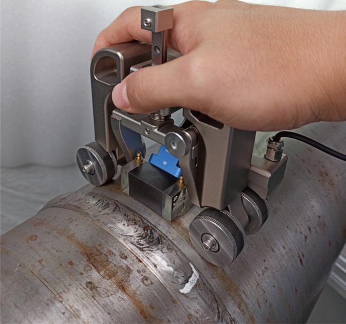
Magnetic adhesion without additional fixing
Frame of adjustable width
MOS43 — Weld Scanner for limited probe travel — specifications
| Parameter | Value |
|---|---|
| Frame range | 22–46 mm |
| Minimum pipe diameter | 60 mm |
CCE-2 — Simple Encoder with frame and handle
The CCE-2 consists of an encoder, a mounting frame and a handle. Compared with the previous generation, the direction of the encoder tip has been changed to face upwards, which extends its life. A hand-shaped grip has been added, and the grip has mounting holes for clipping cables in place — so the cables interfere less with probe coupling.
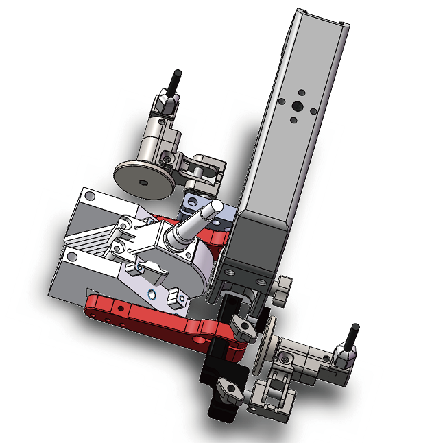
Encoder end facing upwards — longer service life
Mounting holes for cables in the handle
Axial encoder mounting; handle removable where space is limited
CCE-2 — Simple Encoder with frame and handle — specifications
| Parameter | Value |
|---|---|
| Max. clamping frame width | 50 mm |
| Wedge range | 22–50 mm |
CCE-3 — TOFD Simple Bracket Scanner
The CCE-3 is an auxiliary accessory designed to work with TOFD probes in weld inspection, intended to improve inspection accuracy and efficiency. The holder is particularly useful where the working space is narrow.
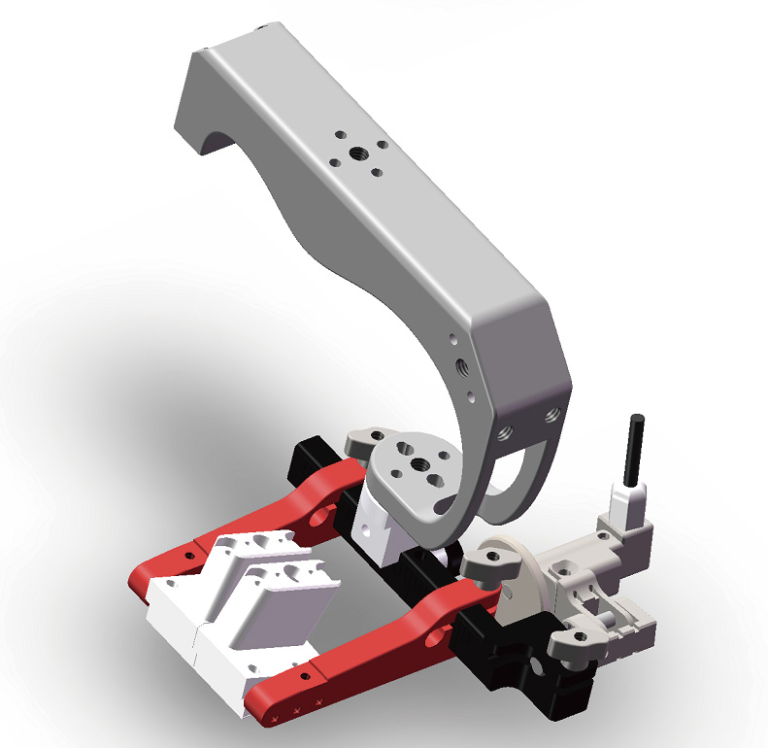
Work in confined conditions
Fixing screws selected to suit the TOFD probe type
Simple and quick adjustment mechanism
CCE-4 — Weld Scanner with side guide
The scanner is designed to inspect tubular components 150 mm in diameter and above. The guide mechanism provides lateral support, so the distance between the probe and the weld stays constant. The support wheel carries the weight of the device, adapts to different diameters and gives smooth movement. The grip is ergonomic and the encoder records the position.
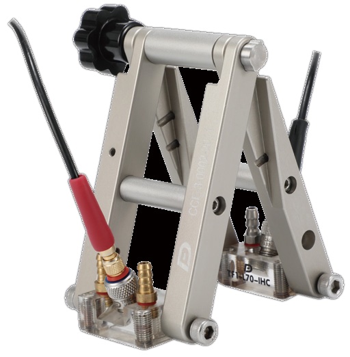
Lateral guide — constant probe distance from the weld
Support wheel adapting to the diameter
Ergonomic grip
Encoder recording the position
CCE-4 — Weld Scanner with side guide — specifications
| Parameter | Value |
|---|---|
| Minimum diameter | 150 mm |
MOS03 — Weld Seam Bilateral Scanner
The MOS03 retains the body design known from the MOS01, which guarantees the same portability and ease of operation. It allows a pair of probes to be mounted for one TOFD group or two phased array groups. The added auxiliary wheel improves probe coupling with the component and increases the stability and reliability of the data.
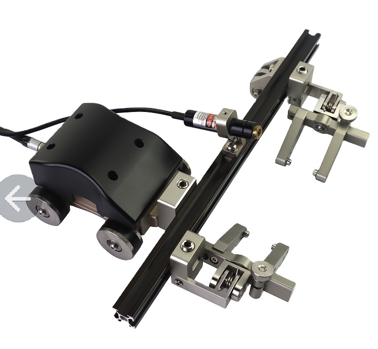
A pair of probes: one TOFD group or two PA groups
Auxiliary wheel improving coupling
Integrated laser — clear reference during circumferential scanning
Probe combination up to 48 mm wide
MOS03 — Weld Seam Bilateral Scanner — specifications
| Parameter | Value |
|---|---|
| Diameter range | pipes above 108 mm |
| Size | 350 × 182 × 43 mm |
| Encoder step | 38 steps/mm |
| IP level | IP67 |
| Wedge width range | 22–42 mm |
FC14 — Axial/Longitudinal Weld Scanner
The FC14 is a scanner intended for pipeline weld inspection. The device mounts four probes at once, supporting inspection of longitudinal and axial welds. The design comprises magnetic wheels for stable adhesion, a water connection supplying couplant to the probe, a mounting frame, a graduated strip giving the operator an accurate position reference, and a support frame.
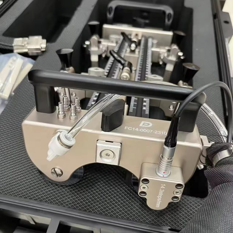
Up to four probes at once
Four independent movable magnetic wheels
Couplant water port
Scale bar — clear position reference
Laser pointer
Optional oblique parallel scanning bracket (codes 2SP0446, 2SP0447)
FC14 — Axial/Longitudinal Weld Scanner — specifications
| Parameter | Value |
|---|---|
| Minimum detection diameter | 150 mm |
FC29 — Simple Circumferential Scanner
The FC29 gives fast positioning and stable adhesion thanks to four magnetic wheels. The laser pointer improves the accuracy of the data collected. The scanner suits pipes of various diameters — in both axial and circumferential mode.
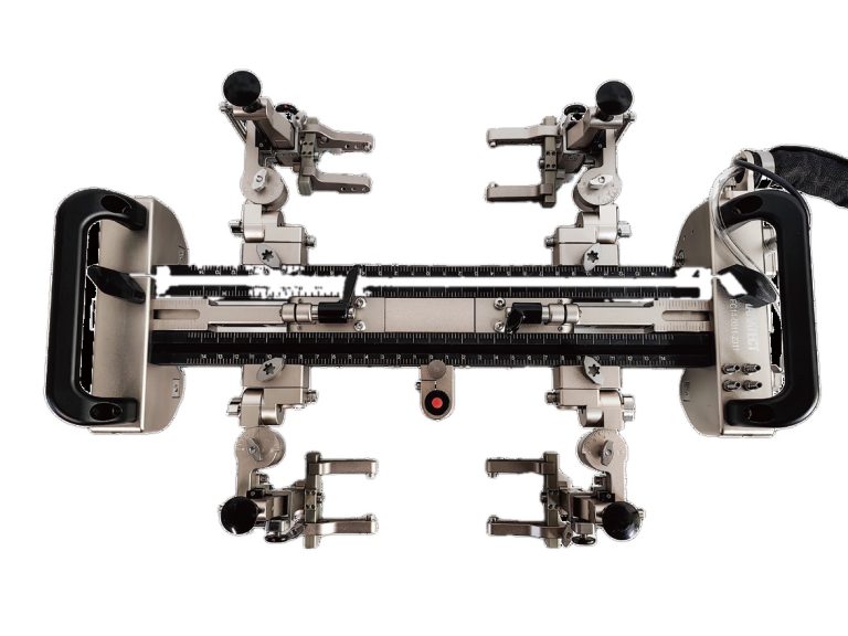
Four magnetic wheels — fast positioning
Laser pointer
FC29 — Simple Circumferential Scanner — specifications
| Parameter | Value |
|---|---|
| Axial mode | diameters above 200 mm |
| Circumferential mode | diameters above 200 mm |
FC30 — Manual Weld Inspection Scanner
The standard configuration of this manual scanner allows four probes to be mounted, and in line with inspection requirements it can be extended to eight probes, which gives flexible inspection schemes.
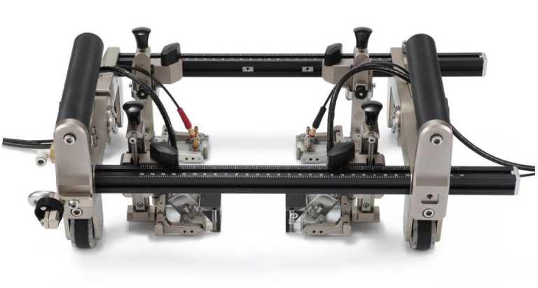
4 probes as standard, expandable to 8
FC26 — Negative Pressure Longitudinal Weld Scanner
The FC26 is a scanner for inspecting longitudinal pipeline welds. Vacuum adhesion technology keeps the scanner from drifting during work, which improves inspection efficiency. The standard stroke is 1000 mm and can be extended to 1500 mm.
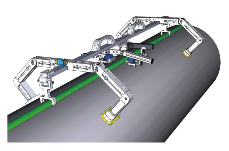
Vacuum adhesion — no drift during work
Four suction cups
2 probes as standard, up to 4 to order
Stroke made to order
FC26 — Negative Pressure Longitudinal Weld Scanner — specifications
| Parameter | Value |
|---|---|
| Standard stroke | 1000 mm (up to 1500 mm to order) |
| Minimum pipe diameter | 500 mm |
| Application range | pipe 500 mm to flat; stainless steel, aluminium, plate |
FC44 — Suction Cup Weld Scanner
The FC44 is a manual scanner suitable for various material types — it overcomes the material limitations of conventional inspection tools. A fixed motion guide prevents probe drift during scanning, which ensures accurate and repeatable results. Manual suction cup technology removes any dependence on a power supply: the vacuum is created by a simple hand operation.
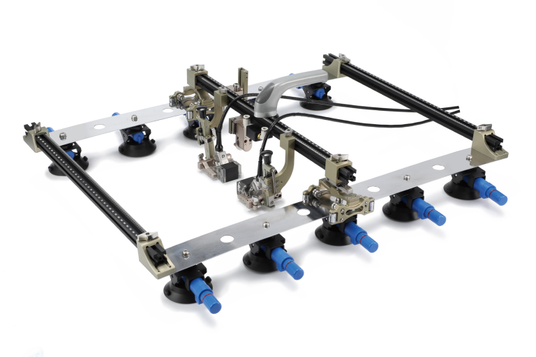
Works on various materials, including non-magnetic ones
Vacuum created by hand — no power supply needed
Fixed motion guide — repeatable results
Useful where the working position changes often
FC44 — Suction Cup Weld Scanner — specifications
| Parameter | Value |
|---|---|
| Weight of the standard set | 4.75 kg |
| Minimum pipe diameter | 600 mm (circumferential welds of straight pipes) |
CRS-7 / CRS-8 — Small-diameter Pipe Weld Scanner
The CRS modular scanner is used to inspect circumferential welds on pipes from 0.8" (20 mm) to 4.5" (114.3 mm) in diameter. It is available in a single-chain version (CRS-7) and a double-chain, double-sided version (CRS-8). The flat, slim chain design, developed for extremely small inspection spaces, allows it to pass through a pipe-to-pipe gap as small as 13 mm.
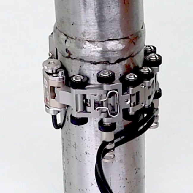
Patented quick-release links — pipe diameter changed by hand, without tools
Slim flat chain — passes a gap from 13 mm
Modular design: main frame, encoder, chain module, lock block
Single- or double-sided version
CRS-7 / CRS-8 — Small-diameter Pipe Weld Scanner — specifications
| Parameter | Value |
|---|---|
| Range | Φ0.8" (20 mm) – Φ4.5" (114.3 mm) |
| Encoder step | 100 steps/mm |
| Width | 55 mm |
| Height | 12 mm |
| IP level | IP65 |
| Operating temperature | −10°C to 50°C |
CRS-14 / CRS-15 — Narrow-width Small-diameter Pipe Weld Scanner
This series of small diameter pipe weld scanners is intended for situations where axial space is limited — the narrowest usable width is 36 mm. The scanner consists of a main frame module, an encoder module with a side outlet, a quick-release chain module and a locking block. By configuring different numbers of chain links it can cover pipes of various diameters.
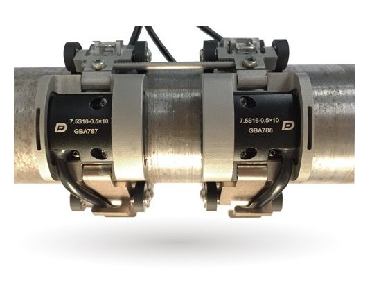
Chain only 36 mm wide
Encoder with a side outlet
Quick-release chain — fewer tools when changing over
CRS-14 single chain, CRS-15 double chain
CRS-14 / CRS-15 — Narrow-width Small-diameter Pipe Weld Scanner — specifications
| Parameter | Value |
|---|---|
| Range | Φ0.8" (20 mm) – Φ4.5" (114.3 mm) |
| Encoder step | 100 steps/mm |
| Width | 36 mm |
| Height | 17 mm |
| IP level | IP65 |
| Operating temperature | −10°C to 50°C |
CRS-34 — Narrow-gap Weld Scanner
The CRS-34 is designed for weld inspection in particularly confined conditions. The two probes working together require a special way of routing the cables. By design, the minimum distance from the weld to the obstructed area on the opposite side should be 15 mm. The distance from the probe face to the weld centreline is adjustable.
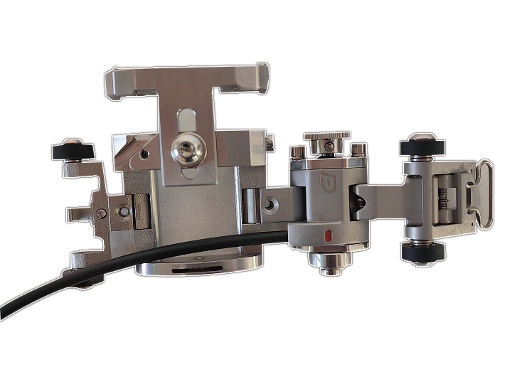
Work in extremely confined conditions
Adjustable probe offset from the weld centreline (2.5–7.5 mm)
Special cable routing for the probes
CRS-34 — Narrow-gap Weld Scanner — specifications
| Parameter | Value |
|---|---|
| Minimum pipe diameter | 25 mm |
| Minimum passable gap | 25 mm |
| Minimum clearance from the obstructed area | 15 mm |
CRS-35 — Elbow Modular Scanner
The CRS-35 scanner is designed to inspect pipelines above 200 mm in diameter. It uses a heavy chain similar to the one in the large-diameter MOS04 scanner, which gives stable travel along the pipeline while carrying two probes. It is also suitable for inspecting elbow welds.
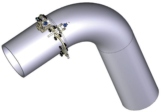
Heavy MOS04-type chain — stable travel
Two probes at once
Elbow weld inspection
CRS-35 — Elbow Modular Scanner — specifications
| Parameter | Value |
|---|---|
| Range | diameters above 200 mm |
| Max. probe holder width | 52 mm |
CRS-25 — Small/Medium Pipeline Weld Scanner
The CRS-25 is designed to inspect pipeline welds with diameters from 50 to 300 mm. It uses a Y15 probe for single-sided scanning, and the probe holder is placed in the middle of the chain, which saves the space needed for scanning. To ensure tight coupling of the wedge with the component, the CRS-25 uses a screw lock, so it is mounted more stably on the pipe surface.
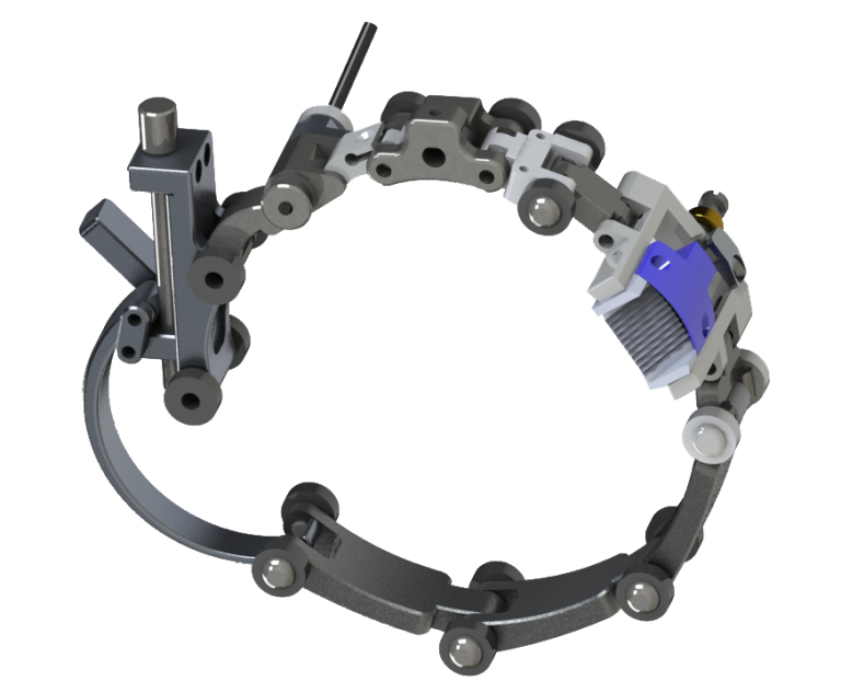
Probe holder on the chain centreline — saves space
Bolt-type locking — stable wedge coupling
Light structure, quick-detachable chain
Supports side-out PA probes 32–48 mm wide
Options: DP2 probe holder (2SP0544), TOFD module (2SP0542), chain extension module to 600 mm (2SP0124, 2SP0151), water feed module (1SP0134)
CRS-25 — Small/Medium Pipeline Weld Scanner — specifications
| Parameter | Value |
|---|---|
| Range | OD 50–300 mm |
| Minimum passable gap | 50 mm |
MOS04 — Large-diameter Pipe Modular Scanner
The MOS04 is a multi-probe system for long-distance pipeline weld inspection, developed for efficient inspection of large areas. It combines a professional inspection mode, a highly compatible mounting frame, a multi-probe configuration, good water resistance and a quick-release chain. The scanner mounts two PA and two TOFD probes at the same time.
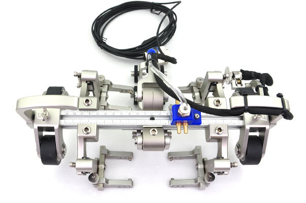
Magnetic and non-magnetic materials
Supports PA and TOFD inspection
Quick-release chain — fast assembly and removal
Manual or automatic version
Other diameters to order
MOS04 — Large-diameter Pipe Modular Scanner — specifications
| Parameter | Value |
|---|---|
| Range | Φ8" (203 mm) – Φ48" (1220 mm) |
| Max. wedge/probe width | 46 mm |
| IP level | IP65 |
| Encoder IP level | IP67 |
| Operating temperature | −10°C to +50°C |
| Storage temperature | −20°C to +60°C |
MOS04-A — Dual-probe Modular Scanner
The MOS04-A uses an innovative quick-release chain design, which makes changing the chain fast and improves working efficiency. The precision mounting frame takes a width of up to 45 mm and fits many two-probe combinations. The scanner can be aligned precisely on the centreline of a weld less than 40 mm wide and less than 6.5 mm high.
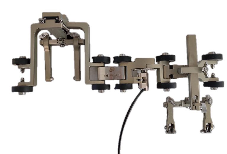
Quick-release chain — fast diameter change
Many two-probe combinations
Precise alignment on the weld centreline
Portable design, for frequently changing working positions
MOS04-A — Dual-probe Modular Scanner — specifications
| Parameter | Value |
|---|---|
| Range | diameters above 100 mm |
| Max. clamping frame width | 45 mm |
| Max. weld width | 40 mm |
| Max. weld height | 6.5 mm |
| IP level | IP67 |
MOS04-DD — Motorized Modular Scanner
The MOS04-DD is used primarily for pipeline weld inspection. It is an electric modular scanner able to carry four probes.
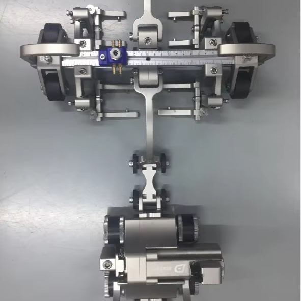
Electric drive
Four probes
MOS04-DD — Motorized Modular Scanner — specifications
| Parameter | Value |
|---|---|
| Non-magnetic materials | 203–700 mm |
| Magnetic materials | 203–1219 mm |
DSC27 — Pipeline Weld Rail-guided Scanner
The scanner is fitted with a matched pipeline guide, and its body is a remotely controlled crawler. It is suitable for metallic and non-metallic pipes. The steel guide band is fixed on the round component and the crawler runs along the guide carrying several pairs of probes. The rail design keeps a constant distance between the probe and the weld, which allows fast, automated inspection of circumferential welds. Different diameters require different guides.
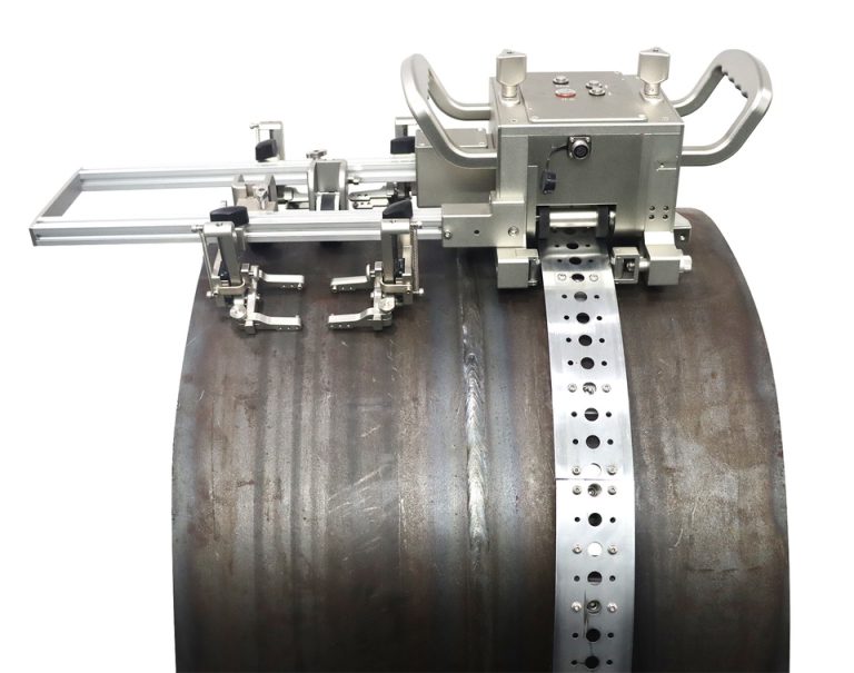
Steel belt guide rail — constant probe-to-weld distance
Wired or wireless remote control
Several probe pairs at once
Metal and non-metal pipes
DSC27 — Pipeline Weld Rail-guided Scanner — specifications
| Parameter | Value |
|---|---|
| Range | OD ≥ 400 mm |
| Crawler speed | 5–60 mm/s |
| Encoder step | 24 steps/mm |
| Repeated positioning accuracy | ± 1 mm |
| IP level | NEMA 4, IP65 |
| Operating temperature | −20°C to +60°C |
| Power Supply | 110/220 V AC or 20–30 V DC |
DSC16 — Ring-shaped Auto-crawler
The DSC16 is a remotely controlled inspection carriage designed to inspect annular components.
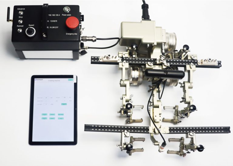
Remote control
Design for annular components
DSC51 — Pipeline Modular Scanner
The DSC51 is used primarily for pipeline weld inspection. It is an electric modular scanner, it can be fitted with two probes and it also works on non-magnetic materials. The standard version has two encoders: one on the chain records the position on the nozzle, the other on the probe stepping axis — which improves the accuracy and reliability of the results. The larger the pipe diameter, the greater the risk of drift during inspection.
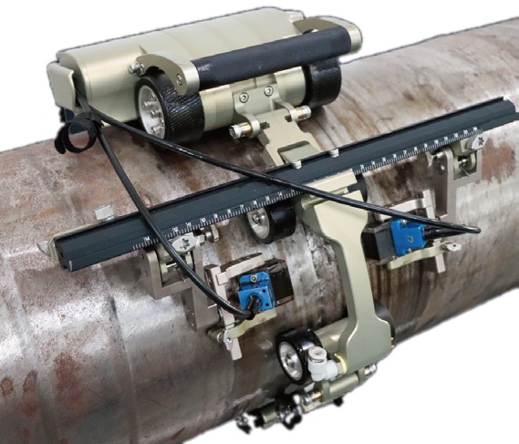
Two encoders: position on the chain and probe stepping axis
Works on non-magnetic materials
Standard version: nozzle from φ50 mm, main pipe from φ500 mm
Custom version: nozzle φ20–50 mm, main pipe from φ500 mm
DSC51 — Pipeline Modular Scanner — specifications
| Parameter | Value |
|---|---|
| Diameter range | 200–800 mm |
| Minimum passable gap | 70 mm |
| Encoder IP rating | IP67 |
MOS07 — Nozzle Joint Scanner
The MOS07 was designed to inspect welds of complex nozzle connections, providing accurate inspection data. The flexible mounting arrangement stably holds a single probe with a maximum mounting width of 48 mm and is compatible with different probe types. The MOS07-DD version is automated: a small magnetic crawler guides the scanner in the axial direction of the nozzle, controlled from buttons on the handle.
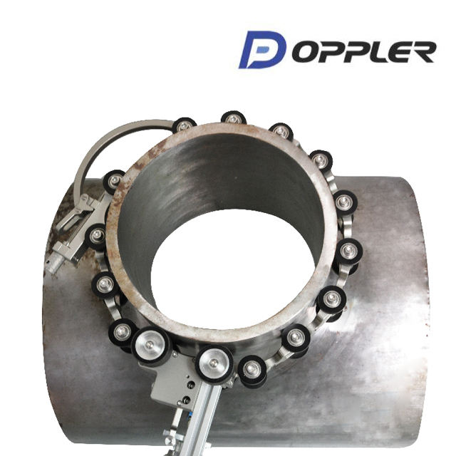
Dual-axis angle and position encoder — accurate probe location relative to the weld
Real-time cross-section at each scanning position
Probe angle adjustable to the weld angle
Quick-release chain
Manual (MOS07) and automatic (MOS07-DD) versions
MOS07 — Nozzle Joint Scanner — specifications
| Parameter | Value |
|---|---|
| Branch pipe diameter | φ100–300 mm |
| Main pipe diameter | ≥ φ600 mm |
| Max. clamping width | 48 mm |
DSC52 — Auto Tube-sheet Weld Scanner
The device is used primarily to inspect welds close to the pipe end. It consists of two basic parts: the scanner body and the controller. It is suitable for inspecting welds in small-diameter bores.
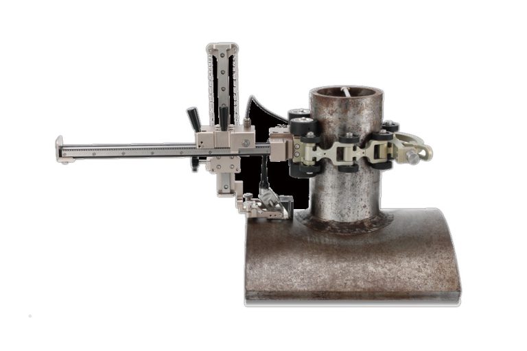
Scanner body + controller
Weld inspection near the ends of small-bore tubes
DSC37 — Motorized Internal Weld Scanner
The DSC37 is a semi-automatic scanner designed to inspect welds inside pipelines. It is particularly useful on complex, small components that manual inspection cannot reach. Structurally it consists of three parts: the drive system, the positioning system and the probe mounting. To suit different diameters, the positioning system and probe mounting are made for the specific diameter.
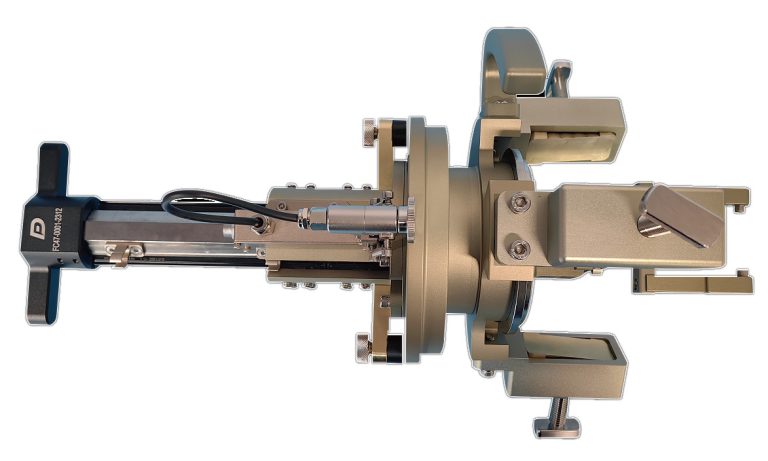
Inspection of internal welds
Positioning system made to the diameter
Components that manual inspection cannot reach
DSC37 — Motorized Internal Weld Scanner — specifications
| Parameter | Value |
|---|---|
| Diameter range | 39–200 mm (to order) |
FC47 — Internal Pipe Weld & Corrosion Scanner
The FC47 is a high-performance manual scanner intended for corrosion and weld inspection, equipped with flexible accessories and compatible with various probes. The universal mounting frame takes a corrosion or weld probe, providing stability and accuracy. The positioning sleeve is made to the size of the component. The axial stepping rod controls probe movement precisely and allows point-by-point inspection, while the rotating seat gives full 360° scanning.
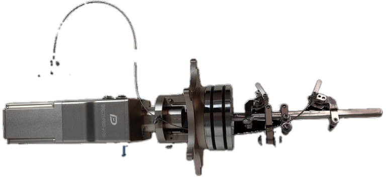
Universal frame for corrosion and weld probes
Positioning sleeve to order
Axial stepping rod — point-by-point inspection
Rotating seat — 360° scanning with no dead zones
Dual encoder arrangement — high accuracy and repeatability
FC47 — Internal Pipe Weld & Corrosion Scanner — specifications
| Parameter | Value |
|---|---|
| Standard pipe inner diameter | 71 mm |
DSC41 — Ring-shaped Component Auto-scanner
The DSC41 is a high-performance electric scanner designed to detect flaws on the face and axial surface of large cylindrical or annular components. Advanced mechanical design gives precise control of a 500 mm stroke on the Y axis and 500 mm on the Z axis. The probe holder covers many inspection scenarios — it takes both conventional and phased array probes.
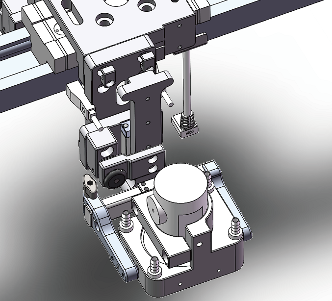
Y axis for face inspection, Z axis for axial inspection
Holder for conventional and phased array probes
Mounting solutions made to the probe size
DSC41 — Ring-shaped Component Auto-scanner — specifications
| Parameter | Value |
|---|---|
| Component diameter range | 2000–6000 mm |
| Y axis stroke | 500 mm |
| Z axis stroke | 500 mm |
| Y and Z axis speed | 5–100 mm/s |
| Standard probe mounting width | 60 mm |
FC54 — Manual XYZ Water-tank Scanner
The FC54 is a precise manual three-axis XYZ scanner with a water tank, able to mount various contact or immersion probes. The tank section can be conveniently removed, which makes contact inspection easier and considerably increases applicability and ease of use. The scanner can also be fitted with a phased array board, which makes manual inspection of water-cooled plates possible.
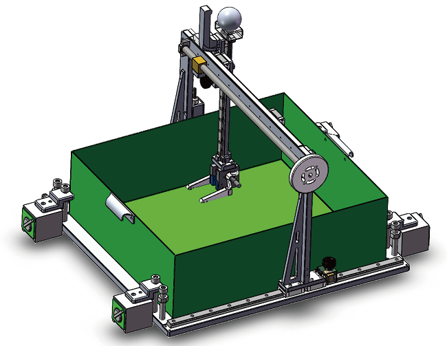
Three XYZ axes, removable water tank
Contact and immersion probes
Optional phased array board
FC54 — Manual XYZ Water-tank Scanner — specifications
| Parameter | Value |
|---|---|
| Usable XY stroke | 350 × 400 mm |
| X axis speed | 5–250 mm/s |
| Y and Z axis speed | 5–100 mm/s |
ENC-10 — Wheel Encoder
A compact encoder designed for present-day industrial inspection requirements — miniature, universal and durable. It is compatible with different probes, and its small size allows work where space is limited or the structure is complex. Rolling steel wheels give smooth, slip-free operation, and the rollers can be changed for non-standard surfaces.
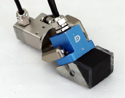
Compatible with many probe types
90-degree angle adjustment with matching accessories
Replaceable rollers for special surfaces
Steel wheels — smooth operation and anti-skid
ENC-10 — Wheel Encoder — specifications
| Parameter | Value |
|---|---|
| IP level | IP67 (dust- and waterproof) |
Applications: Aerospace · Automotive manufacturing · Petrochemicals
LX14 — Cable Encoder
A multi-function, compact auxiliary tool designed to improve the efficiency and accuracy of industrial inspection. The housing is made of aluminium alloy — light, durable and convenient to carry on site. At the end of the cord there is a U-shaped socket allowing different probes or scanners to be connected quickly. Side magnets and a suction cup underneath give double, stable fixing that prevents slipping.
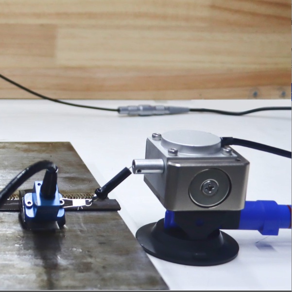
Aluminium alloy housing
U-shaped slot — quick connection of probes and scanners
Double fixing: side magnets + vacuum sucker
LX14 — Cable Encoder — specifications
| Parameter | Value |
|---|---|
| Encoder stroke | 1000 mm |
Applications: Aerospace · Automotive manufacturing · Petrochemicals
MOS05-B — PE Pipe Electrofusion Scanner
The MOS05-B was designed to inspect electrofusion joints of PE pipes. It supports a wedge with a maximum mounting width of 44 mm, which can be made to order. One probe can be mounted. The scanner is suitable for inspecting pipelines with concentric reducers, and the probe and wedge are selected flexibly.
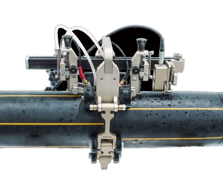
Inspection of PE pipe electrofusion joints
Coaxial reducer pipelines
Other sizes to order
MOS05-B — PE Pipe Electrofusion Scanner — specifications
| Parameter | Value |
|---|---|
| Diameter range | Ф90–400 mm |
| Max. wedge clamping width | 44 mm |
| IP level | IP67 |
MOS05-D — PE Pipe Heat Fusion Scanner
The MOS05-D is a scanner for inspecting butt-fusion joints, designed for the maintenance and quality assurance of PE pipelines. It uses a convenient quick-release chain, so the operator can change the chain quickly to suit working conditions.
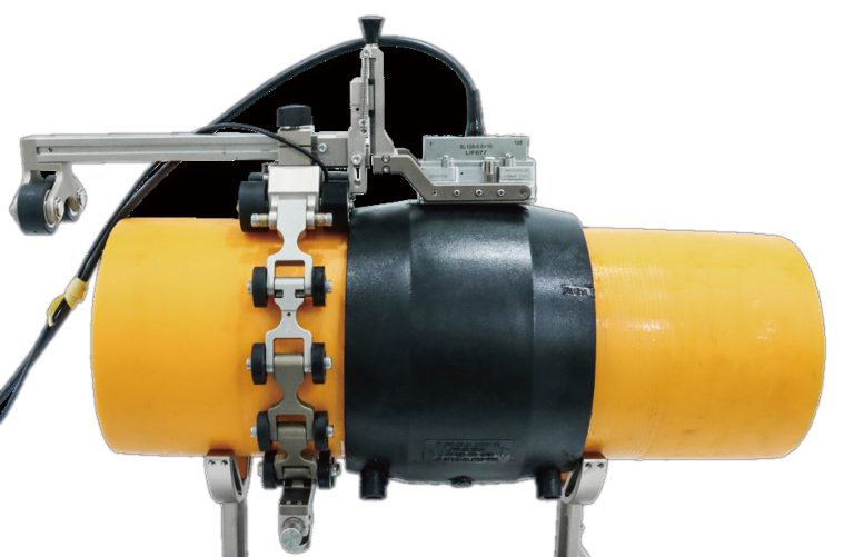
Quick-release chain
Clamping of the TOFD probe matched to PE hot-melt joint inspection
A radial clearance of at least 120 mm is required
MOS05-D — PE Pipe Heat Fusion Scanner — specifications
| Parameter | Value |
|---|---|
| Diameter range | Ф60–400 mm |
PE Pipe Scanner with water jacket
A modular scanner for inspecting PE pipes. The water jacket is made to the size of the component and has a special sealing ring that keeps the water chamber tight and gives very good acoustic coupling. The encoder accurately records the probe position on the pipeline for later data analysis, and the support wheel stabilises the water jacket and helps it slide smoothly along the surface.
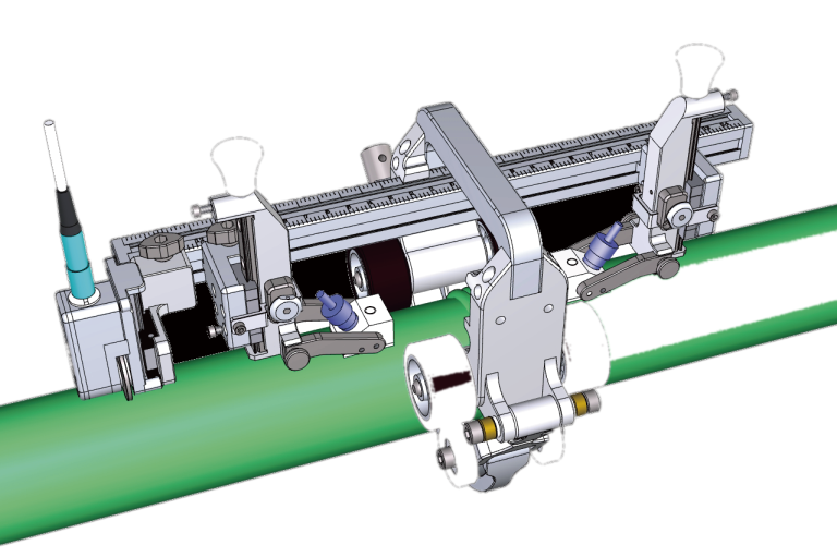
Water jacket with sealing ring — excellent acoustic coupling
Probes in many variants for different procedures
Support wheel stabilising the water jacket
Design avoiding obstacles on the workpiece
PE Pipe Scanner with water jacket — specifications
| Parameter | Value |
|---|---|
| Customisable diameter range | 32–90 mm |
PL — Universal Series
The PL series comprises probes with appropriate sensitivity and resolution, intended for general inspection conditions. Doppler offers three series with different characteristics; PL is the basic choice for most typical tasks.
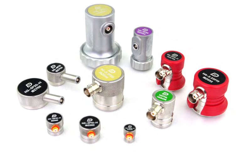
Appropriate sensitivity and resolution
Longer duration of wave, typically 3–5 cycles
Lower bandwidth, typically 30–50%
PL — Universal Series — specifications
Applications: General inspection environments
PH — Short Pulsing Series
The PH series comprises short-pulse probes, ideal for accurate thickness measurement and near-surface inspection. They are characterised by excellent vertical and horizontal resolution and a very small initial pulse dead zone.
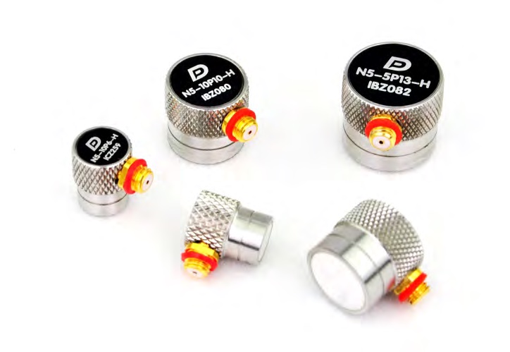
Excellent vertical and horizontal resolution
Tiny blind spot width of the initial pulse
Less sensitivity than the PL and C series
Shorter duration of wave, typically 1.5–2 cycles
Higher bandwidth, typically 80–110%
PH — Short Pulsing Series — specifications
Applications: Precise thickness measurement · Near-surface inspection
C — Composite Series
The C series uses a 1-3 piezocomposite element, which gives high penetration and a high signal-to-noise ratio in coarse-grained materials and fibre-reinforced composites. The low acoustic impedance of the composite allows the probe to be better matched to low-impedance media such as water or plastics.
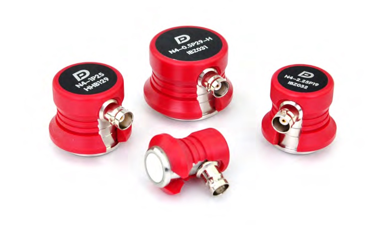
1-3 piezo-composite crystal
Higher sensitivity than the PL and PH series
Shorter duration of wave, typically 2–2.5 cycles
Higher bandwidth, typically 70–110%
Better matching to water and plastics
C — Composite Series — specifications
Applications: Coarse-grained materials · Fibre-reinforced composites
Contact — Wear Resistant Probes
A single-element probe in which the wave strikes perpendicularly in direct contact with the component under test. A stainless steel housing and a wear-resistant protective layer on the face give long service life. The acoustic impedance is well matched to most metals. Available in three performance variants: PL (general purpose), PH (short pulse) and C (composite).
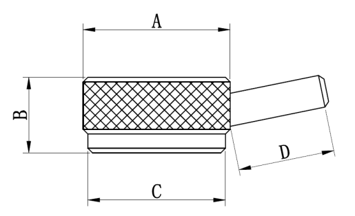
Wear-resistant stainless steel housing
Wear-resistant front protective layer
Good acoustic impedance match with most metals
Three performance types: PL, PH, C
Data sheets to standards: GB/T 27664.2 (CN), EN ISO 22232-2 (EN), ASTM E-1065 (AT)
Contact — Wear Resistant Probes — specifications
Applications: Simple metal structures · Large plates, bars, forgings, metals and non-metals · Vessels, pipes, castings, bars · Sandwich and layered structures · Coarse-grained and highly attenuating materials
Normal Incidence Shear Wave Probes
A normal shear wave probe is a single-element transducer in direct contact with the component that generates a shear wave at perpendicular incidence. The polarisation direction of the shear wave follows the direction of the interface.
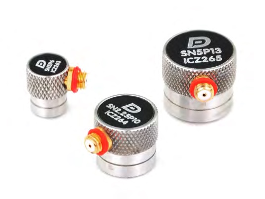
Normal incidence, shear wave inside the workpiece
Sensitivity usually lower than an LW straight probe
Low probe height — suitable for limited space
Requires high-viscosity couplant (order code 6JS0124)
Side-mounted Microdot connector by default, top mounting to order
Normal Incidence Shear Wave Probes — specifications
| Parameter | Value |
|---|---|
| Models | SN5P6, SN5P13 |
| Frequencies | 0.5 / 1 / 2.25 / 2.5 / 4 / 5 MHz |
| Nominal element sizes | 6 / 10 / 13 / 19 / 25 mm |
Applications: Shear wave velocity measurement · Young's and shear modulus calculation · Grain structure analysis
Protective membranes and films
Membranes and protective films fitted to the probe face, extending its life when inspecting rough surfaces. Available as a soft film or a threaded ring.
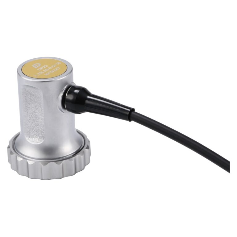
Soft film: 2QT0150, 3SS0058
Threaded collar: 3WK0545, 3WK0564
Protective membranes and films — specifications
| Parameter | Value |
|---|---|
| Nominal element size | 10 mm (0.375") i 24 mm (0.94") |
Dual Element (TR) Probes
TR probes have separate transmitting and receiving crystals, so they create a defined focal distance in the component under test. The absence of an initial pulse dead zone and lower scattering give a higher signal-to-noise ratio in highly attenuating materials.
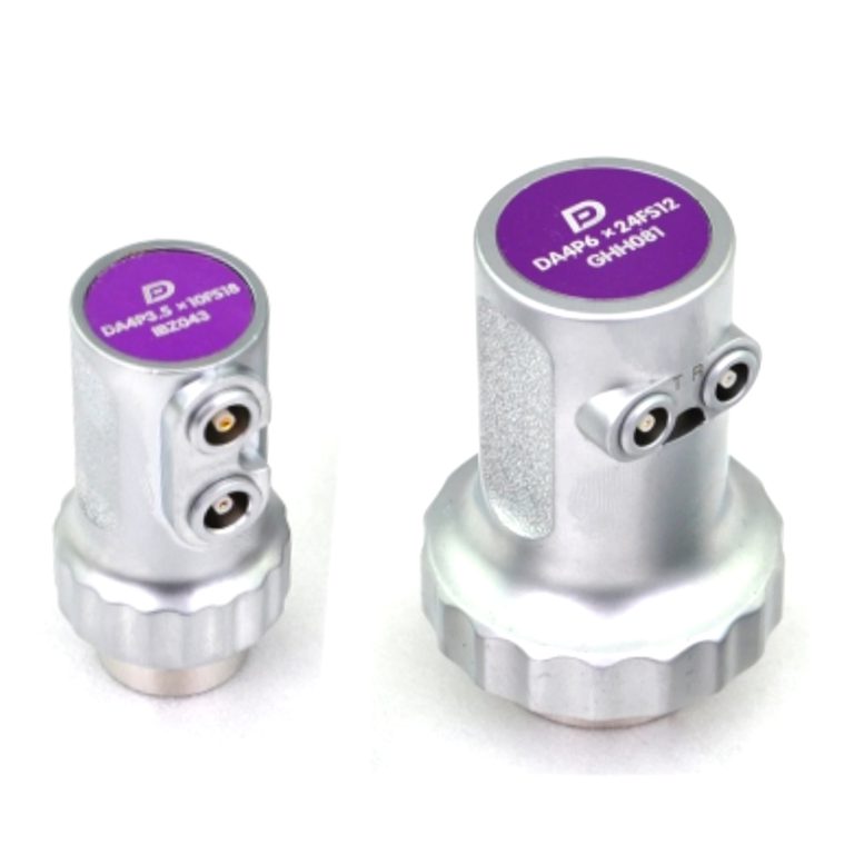
No initial pulse dead zone
Less scattering, higher SNR in high-attenuation materials
Good coupling on curved and rough surfaces
Two performance types: PL (universal) and C (composite)
European standard, Lemo 00 (C5) side mounting connector
Dual Element (TR) Probes — specifications
| Parameter | Value |
|---|---|
| Frequencies | 1–5 MHz |
| Element dimensions | Φ9/2, Φ11/2, 3.5 × 10 mm |
Applications: Corrosion monitoring · Remaining wall thickness measurement · Coating measurement · Near-surface flaw detection · Cracks, pores and inclusions in forgings
Angle Beam Probes and Wedges
Angle beam probes refract the ultrasonic beam and generate a shear or longitudinal wave in the component through a fixed-angle wedge. The probe face can be machined to different shapes to ensure good coupling with the component: AID, CID, AOD and COD.
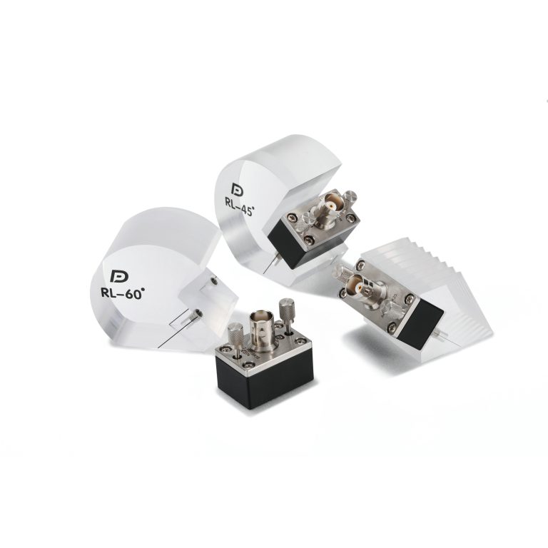
Ergonomic design with durable cast housing
Any theoretical angles customisable
Probe face machined to workpiece shape: AID, CID, AOD, COD
Three performance types: PL, PH, C
Microdot (L5), Lemo 00 (C5) and Lemo 01 (C9) connectors
Angle Beam Probes and Wedges — specifications
| Parameter | Value |
|---|---|
| Standard angles in steel | 45°, 60°, 70°, 90° |
| Nominal element sizes | Φ6, Φ10, Φ13, Φ25 mm and 13×25, 19×25 mm |
| SL delay lines | SL-Φ13, SL-13x25, SL-19x25, SL-Φ25 for 45–90° angles |
| Minimum size | 3 × 4 mm |
Applications: Welded joint inspection · Pipes, pressure vessels, storage tanks · Turbine blades · Wheel axles, castings, forgings · Railway wheels and rails
TRL Angle Beam Probes
TRL probes have separate transmitting and receiving crystals, refract the beam at an angle and create a defined focal distance in the component under test. All refraction angles are longitudinal waves and can be made for any angle that is possible within ultrasonic theory.
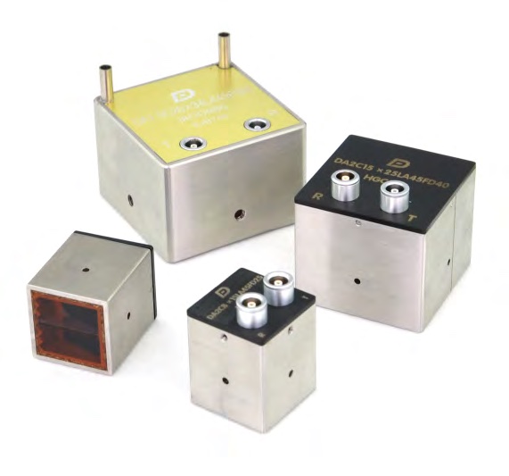
No initial pulse dead zone
Less scattering, higher SNR in high-attenuation materials
All refraction angles are longitudinal waves, any angle customisable
Probe face machined to workpiece shape: AID, CID, AOD, COD
Two performance types: PL (universal) and R (high performance)
TRL Angle Beam Probes — specifications
| Parameter | Value |
|---|---|
| Example models | DA1.5C20X34LA45FS80-IAOD980, DA2C15X25LA45FD40, DA2C8X14LA45FD25 |
| Element dimensions | 7×10, 8×14, 10×18, 15×25, 20×34 mm |
Delay Line Probes
Probes with a replaceable delay line at the front, with the wave striking the component perpendicularly. The wide bandwidth and narrow pulse together with the delay line give excellent near-surface resolution. The thickness of the delay line determines the maximum thickness of the component under test — the manufacturer offers three thicknesses.
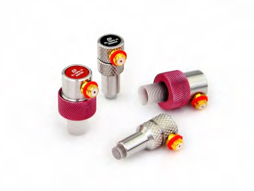
Replaceable delay lines (available separately)
High bandwidth and narrow pulse
Higher frequency increases detection resolution
Delay line length and material customisable
Microdot (L5) side mounting connector
Delay Line Probes — specifications
| Parameter | Value |
|---|---|
| Frequencies | 2.25 / 3.5 / 5 / 10 / 15 / 20 MHz |
| Nominal element sizes | 3 / 5 / 6 / 13 mm |
| Default length | 5.5 mm for Φ3 mm; 12.7 mm for Φ5/6/13 mm |
Applications: Direct flaw detection · Accurate thickness measurement · Near-surface flaw detection · Curved surface inspection · Inspection of very thin components
TOFD Probes
A TOFD probe with a delay line generates a refracted longitudinal wave in steel and uses the time-of-flight diffraction technique to characterise cracks. The design allows the probe and the delay line to be changed quickly.
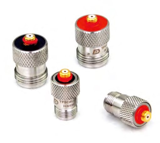
High damping and wide bandwidth
High efficiency for weld inspection
Quick change of probe and delay line
IHC delay lines — irrigation, holes and carbides
TOFD Probes — specifications
| Parameter | Value |
|---|---|
| Delay lines | TF1 series, e.g. TF1-L45-IHC |
Applications: Plate butt weld inspection · Directionally irregular defects · Near-surface defect detection
High Temperature Delay Line Wedges
A single-element probe with a replaceable delay line, intended for inspection in high temperature environments. Types ZH and AH are available, as well as HT1 and HT2 variants with different heat resistance and maximum continuous operating time.
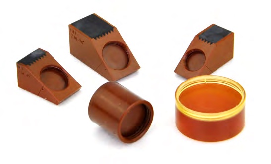
Replaceable delay line
ZH and AH types
Intermittent contact with heated workpieces
High Temperature Delay Line Probes — specifications
| Parameter | Value |
|---|---|
| HT1 (ZH type) | 170°C / max. 10 min |
| HT2 (ZH type) | 500°C / max. 10 min |
| HT1 (AH type) | 130°C / max. 10 min |
| HT2 (AH type) | 270°C / max. 10 min |
| Example models | HT1-Φ19-13, HT2-Φ10-45°, HT2-Φ10-70°, HT2-Φ6-60°, HT2-Φ13-25 |
Applications: Intermittent contact with hot workpieces — castings, forgings · Direct flaw detection · Curved surface inspection
Immersion Probes
Probes designed to be fully or partly immersed in water or another liquid in order to generate the ultrasonic beam. Available in the European (I1) and North American (I3) standards.
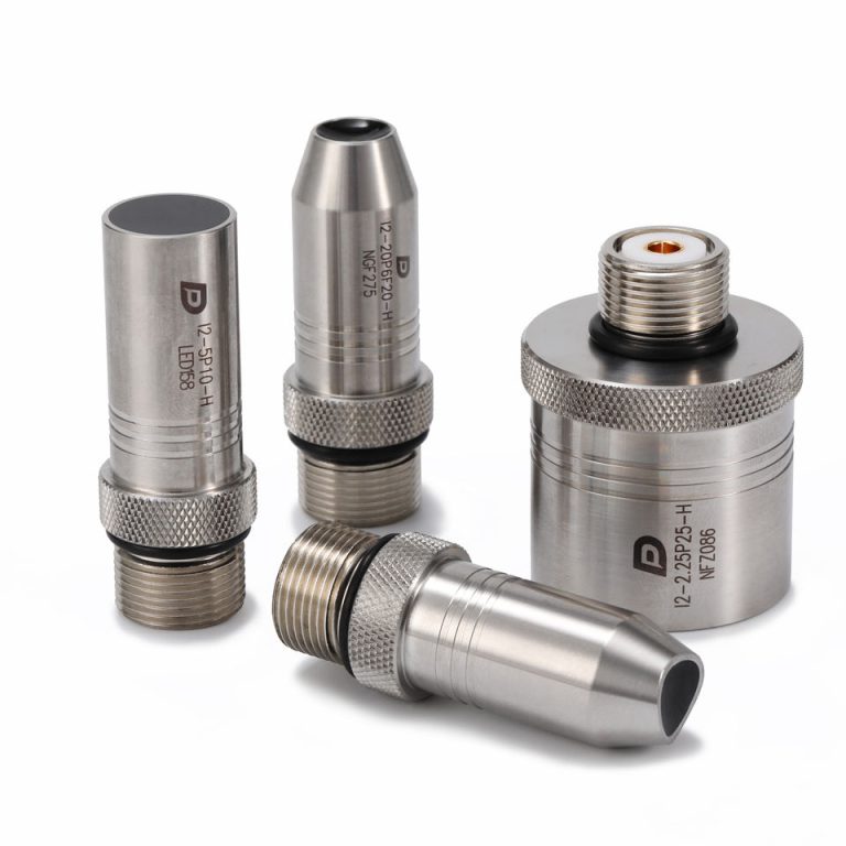
European standard I1 — top mounting, 1.8 m or 2.5 m cable with Lemo 01 (C9) connector
North America standard I3 — 9.7 mm outer diameter, for limited detection environments
Top-mounted Microdot (L5), non-waterproof (I3)
Three performance types: PL, PH, C
Immersion Probes — specifications
| Parameter | Value |
|---|---|
| Frequencies | 1–25 MHz (I1: 1/2/4/5/10/15/20 MHz; I3: 2.25/3.5/5/10/15/20/25 MHz) |
| Nominal element sizes | 3 / 5 / 6 / 10 / 20 mm |
| Example model | I1-5P10 |
High Frequency Probes 20–50 MHz
A high frequency probe is a single-element transducer with a frequency above 20 MHz. The range covers contact, immersion and self-focusing immersion variants. Contact and immersion probes have integrated delay lines, while self-focusing immersion probes have neither a delay line nor a lens.
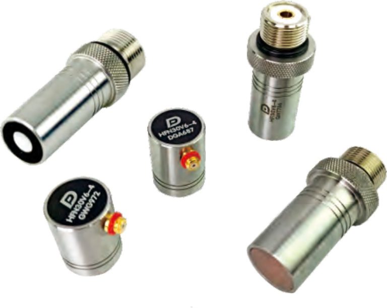
Broadband and narrow pulse — excellent near-surface, vertical and horizontal resolution
Very small focal spot diameter
Side-mounted Microdot (contact), top-mounted UHF (immersion)
High Frequency Probes 20–50 MHz — specifications
| Parameter | Value |
|---|---|
| Frequency range | 20–50 MHz |
| Minimum measurable thickness | 0.05 mm in steel at 50 MHz (in thickness measurement mode, under ideal conditions) |
Applications: Fine surface cracks · Inspections requiring high resolution — small cracks and pores · Scanning acoustic microscopy
Air-coupling Probes (ACU)
Air-coupled probes perform non-contact ultrasonic testing (ACU) with high sensitivity and a high signal-to-noise ratio. An optional built-in 60 dB amplifier with a USB interface is available.
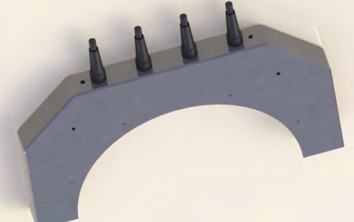
Non-contact inspection — no couplant
High sensitivity and high signal-to-noise ratio
Optional 60 dB built-in amplifier, USB interface
Focusing and water-mist series customisable
Air-coupling Probes (ACU) — specifications
| Parameter | Value |
|---|---|
| Models | AB0.25C24NF-T / -R (transmit / receive), AB0.42C24NF-T / -R |
| Frequencies | 250 kHz i 420 kHz |
| Active Aperture | 24 mm |
Probes for Custom and Specific Applications
From the outset, the manufacturer’s strength has been the design of non-standard and special probes. Application engineers and probe designers work together with the customer to match the solution to the specific application.
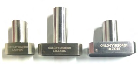
Variable angle probe — adjustable 0–90°, for measuring angle and performance before finalising products
1T3R steel plate probe — automatic plate inspection in the steel industry
20 MHz high frequency immersion probe — areas difficult to penetrate
Special 15 MHz immersion probe, housing only φ5 × 5 mm — thickness measurement of metal pipes (≤ 0.5 mm) under fast rotation
Hollow shaft probe — railway, rails and wheel connecting-rod shafts
Wheeled industrial probe
Water filling probe — coupling through a transparent conical tube
Hollow focusing probe and low frequency probe
Cables and connectors
A probe cable consists of a coaxial conductor (core + insulation + shield) and two connectors joining the probe to the instrument, used to transmit the electrical signal. Unless stated otherwise, the impedance of all cables is 50 ohms.
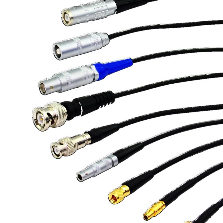
Connectors: BNC (Q9), BNC (Q6), Microdot (L5), Lemo-00 (C5), Lemo-1 (C9), Lemo mini, right-angle MCX, UHF
Waterproof versions of Lemo-1 and UHF
Coaxial cables: RG174, RG178, RG316, RG58
Cable length to order
Special cables to order
Cables and connectors — specifications
| Parameter | Value |
|---|---|
| Impedance | 50 Ω |
Hyperbolic Ultrasonic Transducers
The main feature of a hyperbolic transducer is its aspherical, focusing active surface, usually larger than in conventional transducers. The shape of the transducer is determined by calculation — it defines a surface from which the wave reaches the flaw from every point at the same time. The transducer is designed for a specific application.
Why aspherical focusing
Some critical components that have to be inspected by non-destructive methods are made of materials regarded as difficult for ultrasound because of high attenuation or inhomogeneity — for example titanium or austenitic steel. Detecting the size and depth of a flaw requires high lateral resolution, and combining that resolution with a long sound path and a low frequency calls for a transducer with a large aperture and focusing. The inspection is usually carried out across an interface that causes defocusing, which is why an aspherical transducer is used, focusing at a precise point in the given material through a toroidal surface.
Operating principle
Across a flat, cylindrical or annular interface, the effective focusing area of the aspherical surface is determined by calculation in order to obtain the best focusing effect at the required refraction angle at a defined position in the material. The broadband aperture of the transducer combined with the hyperboloid significantly improves lateral resolution and the signal-to-noise ratio. This technique normally uses the immersion pulse-echo method.
Features
Piezocomposite technology · centre frequency (−6 dB) from 1 MHz to 10 MHz · relative bandwidth (−6 dB) from 60% to 90% · acoustic impedance matched to water, which compared with solid piezoceramic gives better energy transfer and, together with high electroacoustic efficiency, raises the sensitivity level by 10 to 50 dB · waterproof stainless steel housing and waterproof UHF connector.
Advantage
Very high resolution and signal-to-noise ratio · thanks to piezocomposite technology the beam shape closely matches the simulation · hyperbolic surfaces allow flexible focusing and beam steering at high resolution.
Applications: inspection of thick-walled components and inhomogeneous materials · multi-zone inspection of semi-finished products · inspection of heavy plate · inspection of large forgings · inspection of nuclear vessels.
Phased array inspection — application examples
A selection of cases from the manufacturer’s application documentation, chosen for the industries X-TEST serves: power generation, pipelines, bridges and steel structures, rail, automotive, aerospace and wind energy. Each description corresponds to a real inspection carried out with Doppler equipment.
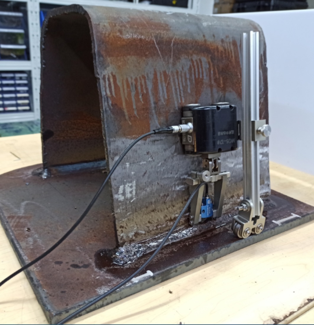
Fillet welds of 8 mm U-ribs with a required penetration depth. Inspection carried out with limited access to the surface.
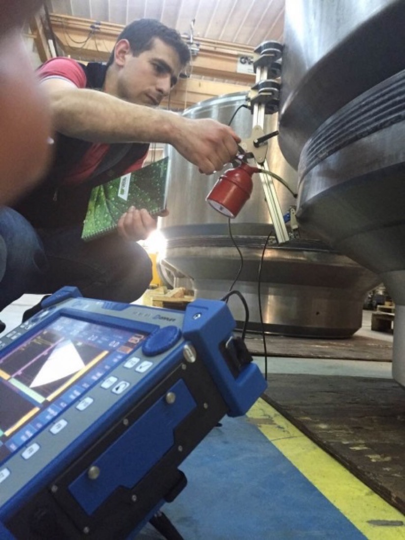
Inspection of joints connecting components of different thickness, where conventional UT has limited coverage.
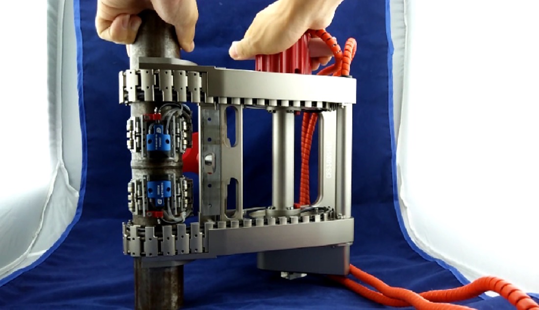
Fast double-sided inspection using a scanner clamped on the pipe wall; also covers elbow welds of 50–100 mm diameter.
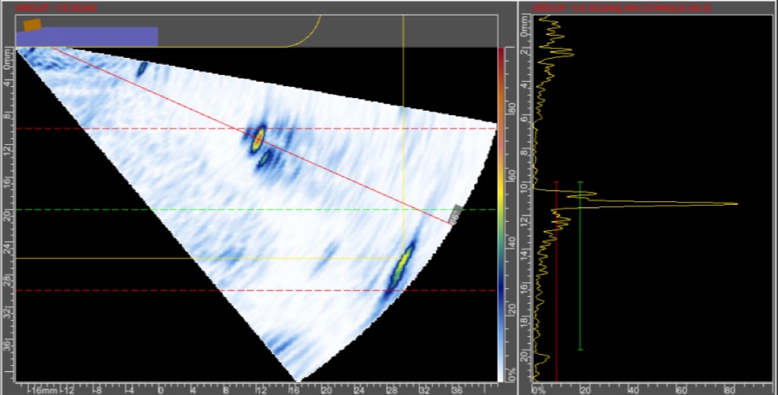
Nozzles from Φ100 to Φ300 mm on a main pipe from Φ600 mm — sector image with flaw location.
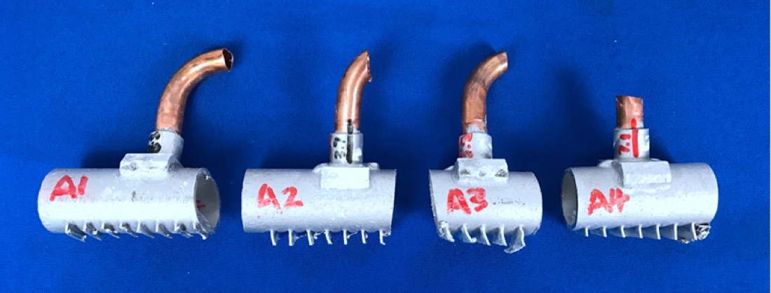
Inspection of the root run in dissimilar material joints on reference specimens.
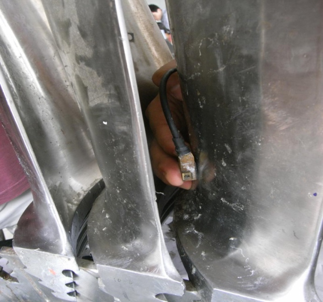
Inspection of the roots of power turbine blades — fir-tree, fork and dovetail types.
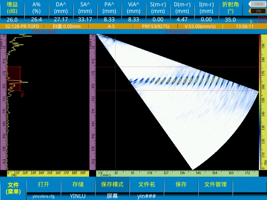
Bolt inspection without disassembly, with a single coupling; S-scan and C-scan images of a sound bolt and a bolt with a flaw.
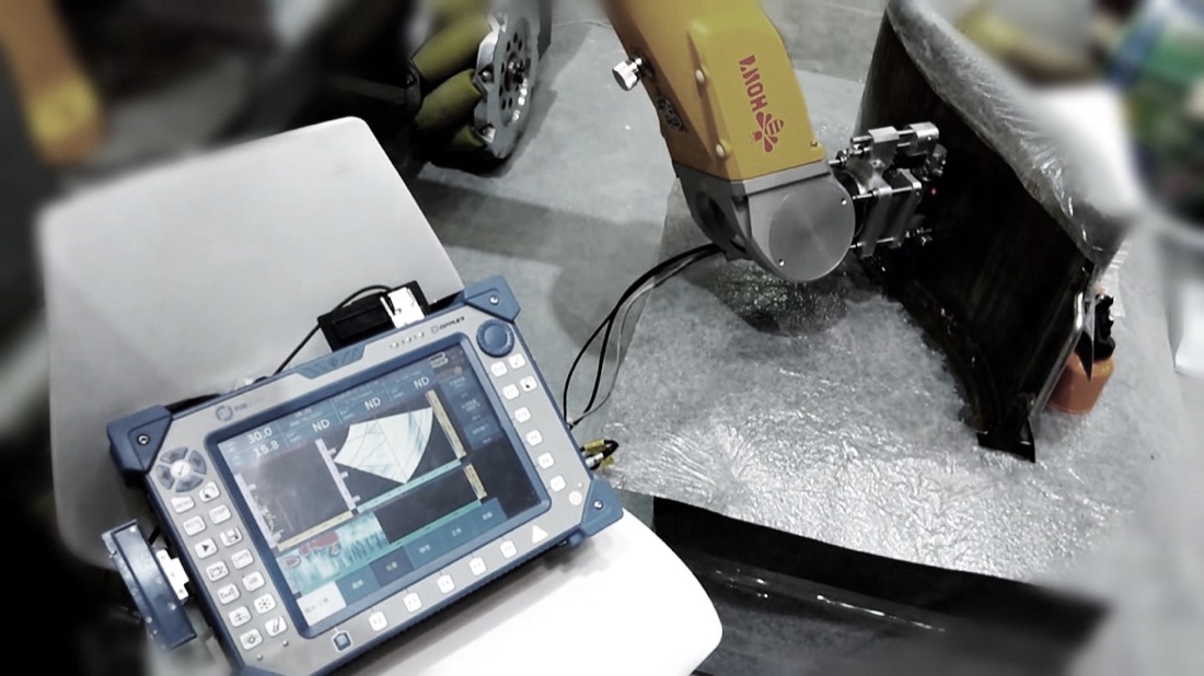
Fatigue cracks in the blade root connection bolts — inspection with a dedicated annular hollow probe.
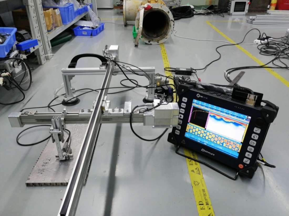
Honeycomb core structures: metal and composite skins, detection of disbonds in the adhesive layer.
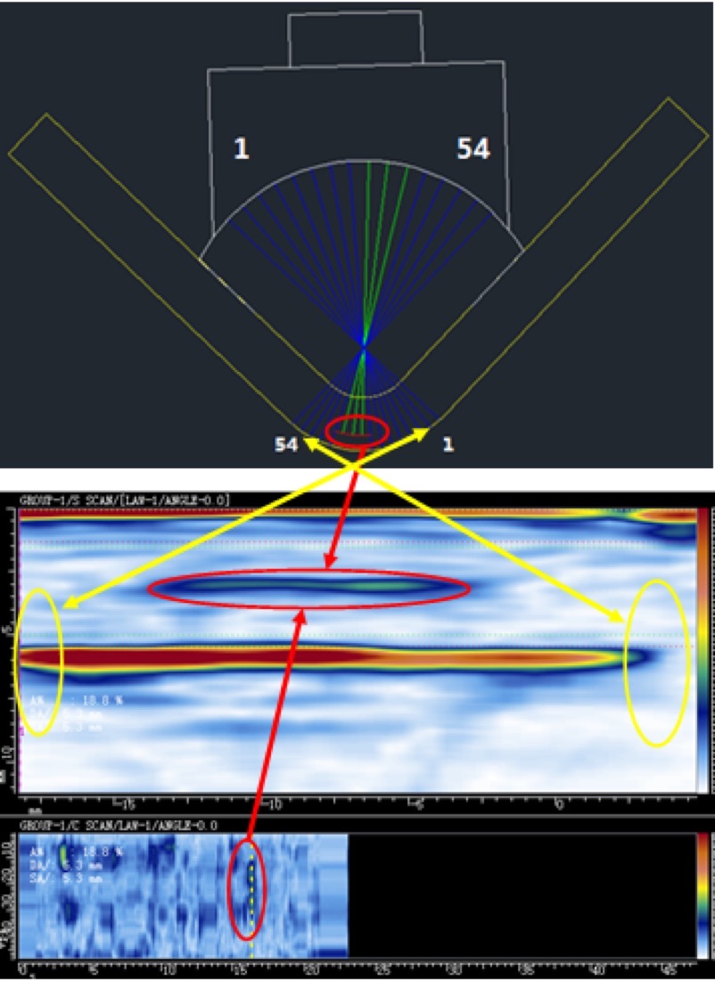
T-profiles and R corners of composite components — a single pass covers the whole corner area.
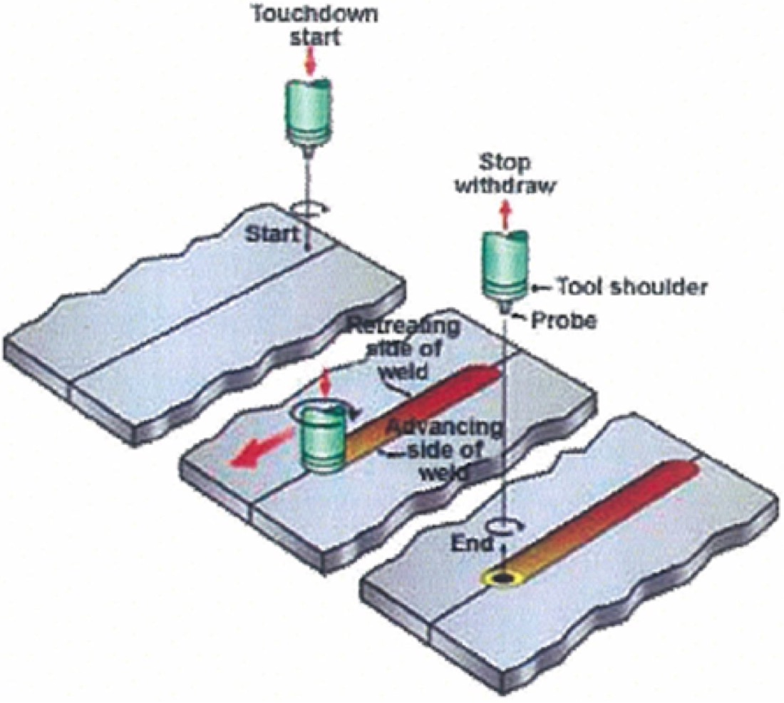
Inspection of friction stir welded joints used in aerospace and rail structures.
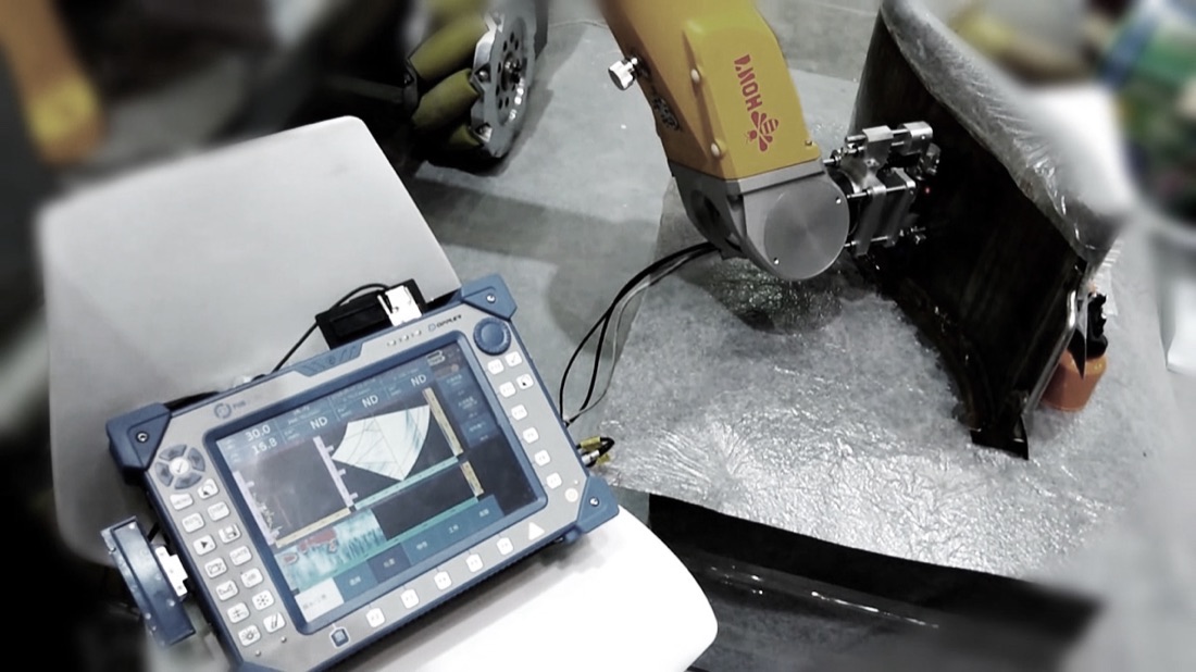
Butt-fusion joints of polyethylene pipelines — detection of solid contamination and cold welds.
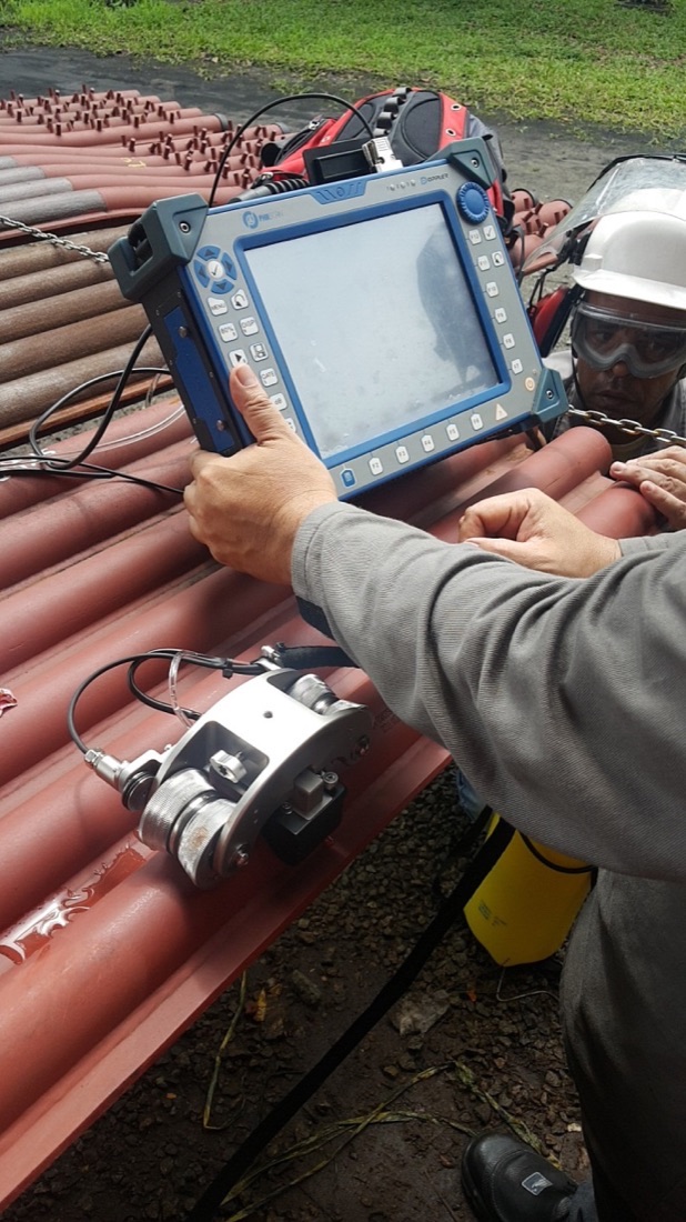
Measurement of corrosion loss on power boiler water wall tubes under field conditions.

Quality control of the cell adhesive layer — images of a typical disbond and of a sound joint.
Brake suspension seats on high-speed multiple unit bogies.
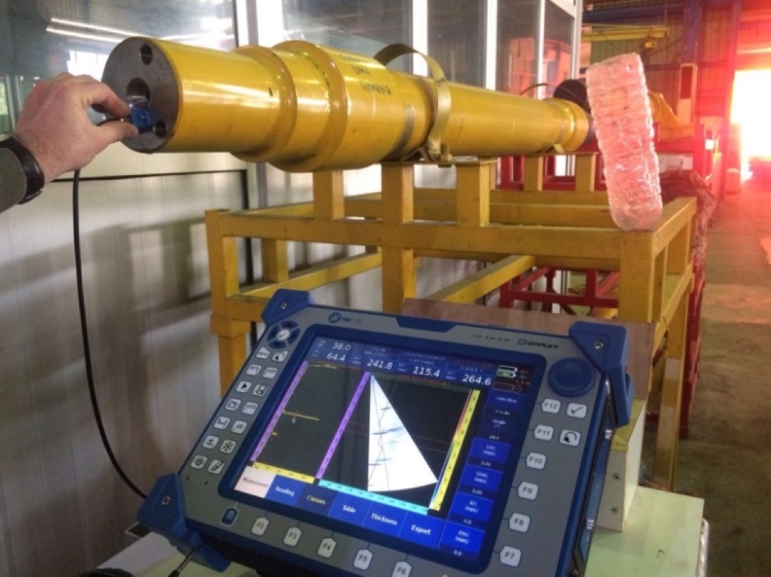
Inspection of locomotive axles under workshop conditions.
Assessment of the bond quality between layers in copper–steel composite materials.
Would you like a quote?
All Doppler equipment is in our shop — with specifications, photos and an inquiry form. X-TEST is the exclusive distributor for Poland, Lithuania, Latvia and Estonia.