
Shop · Category
Phased array flaw detectors (PAUT)
Portable PAUT flaw detectors with TFM imaging and TOFD support.
 Exclusive distributor of the DOPPLER brand
PL · LT · LV · EE
Application
Inspected object
Inspection technique
Showing all 5 results
-
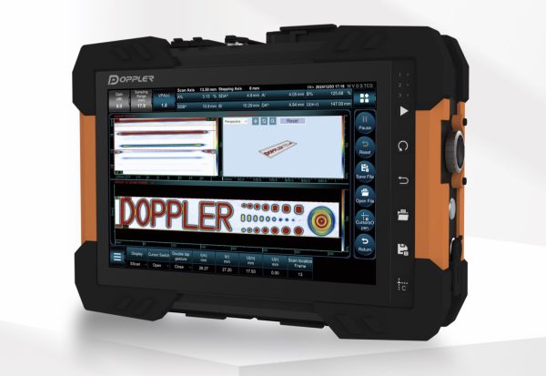
Novascan V3 — phased array flaw detector
Ask about this product -
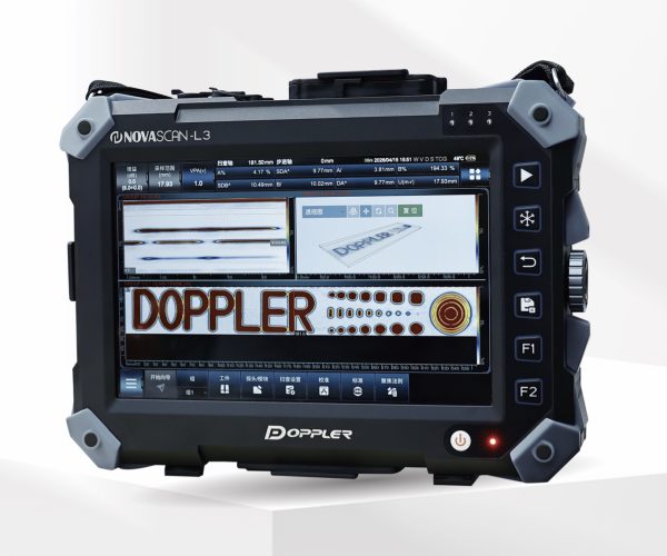
Novascan L3 — lightweight phased array flaw detector
Ask about this product -
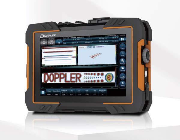
Novascan V2 — phased array flaw detector
Ask about this product -
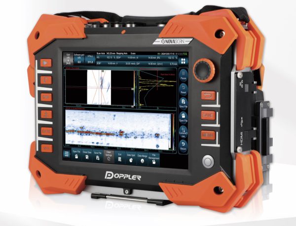
Novascan V1 — phased array flaw detector
Ask about this product -
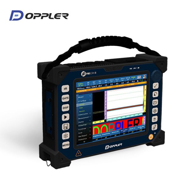
Phascan II — phased array flaw detector
Ask about this product
Choosing a phased array flaw detector
What an instrument can do is set first of all by its channel configuration, written as receive channels over transmit channels. A 32/128 unit drives a 128-element probe but fires 32 elements at a time. More receive channels mean a larger active aperture, so deeper focusing and fewer probe positions on the weld. The second number is the pulse repetition frequency: it sets how fast the scanner may travel before data lines are lost.
The whole Doppler family is below. Every model records encoded data and builds C-scans; they differ in how far the configuration goes and how much imaging they compute in real time.
| Model | Channels | PRF | Bandwidth | What sets it apart |
|---|---|---|---|---|
| FLEXSCAN | 16/64PR, 32/64PR | per configuration | per configuration | 43% smaller and 22% lighter than the previous series; 8.4" screen, PA, TOFD and UT at once |
| Novascan L3 | 32/64PR, 16/64PR | 20 kHz | 0.5–20 MHz | 2.7 kg, 10.1" 1920 × 1200 screen, FMC-TFM and PWI-TFM plus TOFD in one unit |
| Phascan II | 32/128PR | per configuration | per configuration | TFM and FMC, 2D matrix probes, 3D simulation, CAD import, 128 GB SSD, files up to 4 GB |
| Novascan V1 | 16/64PR to 32/128PR | 40 kHz | 0.5–20 MHz | 6 kg, FMC-TFM and PWI-TFM, two UT/TOFD channels next to the PA module, 10.4" screen |
| Novascan V2 | 16/128PR to 64/128PR | 40 kHz | 0.3–25 MHz | 4.9 kg, 200 MHz sampling, live FMC-TFM and PWI-TFM, 12.1" screen |
| Novascan V3 | 32/64PR to 64/128PR | 40 kHz | 0.18–27 MHz | 5.1 kg, 200 V pulser, the only one with FMC-PCI and PWI-PCI, AIM sound-field map — the top model |
When TFM is actually needed
Conventional phased array sums the signals inside the instrument, following focal laws set before the inspection. FMC records every transmit–receive combination separately: a 64-element probe yields 4096 waveforms at each position. Only then does the TFM algorithm reconstruct an image focused at every point of the grid, instead of at one chosen depth.
The gain is real for small discontinuities, coarse-grained materials and geometries where the echo returns from an awkward angle. So is the cost: processing that much data slows scanning down. On pipeline girth welds the zonal technique runs at 50–100 mm/s, while FMC/TFM systems typically work at 25–30 mm/s (figures from a published paper on pipeline AUT systems). In practice TFM is switched on where ordinary PA leaves doubt, not instead of it.
TFM imaging, in the FMC-TFM and PWI-TFM variants, is available on every Novascan we sell: Novascan L3, Novascan V1, Novascan V2 and Novascan V3. PCI goes one step further, building the image from phase coherence instead of amplitude — it pulls small, awkwardly oriented flaws out of material noise. FMC-PCI and PWI-PCI are available on Novascan V3 only, the newest and most capable model in the family. Phascan II computes TFM as well. FLEXSCAN works in phased array, TOFD and conventional UT — a conventional UT channel being something every instrument on this list has.
TFM or PCI — what each image shows
Both techniques compute the image from the same data: the matrix of raw A-scans captured with FMC or PWI. FMC fires the elements one by one and records every combination — 4096 waveforms with a 64-element probe. PWI sends a plane wave at several angles instead, so acquisition is several times faster and the image refreshes more often. TFM and PCI only part company at the processing stage: TFM computes the amplitude of the summed signal for each pixel, PCI computes the phase coherence factor and ignores echo height altogether.
| TFM | PCI | |
|---|---|---|
| What it computes | acoustic pressure amplitude | phase coherence factor of the signals |
| Gain | needs TCG / DAC calibration | gain-free — immune to saturation and attenuation |
| Small scattering flaws | low amplitude, easy to miss | very high sensitivity, bright indication |
| Pore nests, HTHA, SCC | needs extra gain and a chosen colour palette | unambiguous indications, grain noise suppressed |
| Geometry and backwall | clear: backwall, root, weld cap | weak — smooth flat edges show poorly |
| Standards | PN-EN ISO 23864, 23865 and 19285 | complementary technique, no standard of its own |
How this works in practice
The techniques do not compete, they complement each other. TFM is what goes into the acceptance report: it has standardised criteria and renders the joint geometry faithfully. PCI runs on the same data as a probing tool — wherever the flaw scatters the wave instead of reflecting it: porosity, early stages of high-temperature hydrogen attack, branched stress corrosion cracking in austenitic steel. On lack of sidewall fusion, TFM shows the reflection off the fusion face while PCI brings out the diffraction signals from both of its tips, which makes height sizing easier.
Instruments that compute both also build a hybrid image: TFM amplitude weighted by the PCI coherence factor. Evaluation stays amplitude-based and standard-compliant, while structural noise in coarse-grained material fades out. In our range that combination comes from Novascan V3 — the only model with PCI — and from the ROBUST F1 board in automated systems.
Frequently asked questions
How many channels are enough for weld inspection?
For butt welds in plate and pipe of ordinary wall thickness, 16/64 or 32/64 is enough. A 32/128 configuration and above pays off on thick walls, on corrosion mapping with a wide probe, and whenever one pass has to cover the full weld. For automated systems we go further: ROBUST F1 comes in 128/128 and 256/256 versions.
Can phased array replace radiography?
On pipeline girth welds it already does. In a comparison over 202 welds on a 30" pipeline, the phased array system found every indication reported by the conventional multi-probe system and sized length and height at least as well (published AUT comparison). Whether the substitution is allowed is decided by the acceptance standard and the client, not by the equipment.
Can one instrument run PA and TOFD together?
Yes. The Novascan models carry two UT/TOFD channels beside the phased array module, and Phascan II and FLEXSCAN run phased array, TOFD and conventional UT at the same time — one screen shows the sector scan and the TOFD image from the same pass. You need TOFD probes and separate wedges for it.
What else is needed besides the instrument?
A probe with a wedge from Wedges and delay lines matched to the geometry, an encoder from Encoders for ultrasonic scanners, a cable and a calibration block. For encoded inspection you also need a scanner — Manual and modular scanners for UT or Scanning crawlers — to keep the probe on a repeatable path.